
Fiber patch cords are essential components in modern optical communication systems, acting as the final connection between critical network devices. Whether you are working in a data center, enterprise LAN, or FTTH deployment, proper installation directly impacts signal quality, network stability, and long-term reliability.
Even though fiber patch cords are simple in structure, incorrect handling during installation can lead to significant performance degradation. This guide provides a comprehensive, step-by-step explanation to help you install fiber patch cords correctly and avoid common mistakes.
What Is a Fiber Patch Cord?

A fiber patch cord, also known as a fiber jumper, is a short optical cable terminated with connectors on both ends. It is used to connect optical equipment such as switches, patch panels, OLTs, and ONTs.
These cables serve as the critical link in the optical signal path, meaning their quality and installation directly affect overall network performance.
There are two main types:
Single mode fiber patch cord – Designed for long-distance transmission with minimal signal loss, typically used in telecom and FTTH networks.
Multimode fiber patch cable – Suitable for short-distance communication, commonly used in data centers and LAN environments due to lower cost.
Choosing the correct type is essential, as mismatched fiber types can result in severe signal loss or complete communication failure.
Why Proper Installation Matters
Proper installation is not just a best practice—it is a requirement for maintaining network integrity.
When fiber patch cords are installed correctly, they ensure:
Consistent low insertion loss, which keeps signal strength stable across connections
Minimal return loss, preventing signal reflections that can interfere with transmission
Reliable high-speed data transfer, especially in high-bandwidth applications
Longer service life, reducing the need for frequent replacements
On the other hand, poor installation practices can introduce hidden problems such as microbending, contamination, or connector misalignment. These issues may not cause immediate failure but can gradually degrade network performance and make troubleshooting more difficult.
Tools and Materials Needed

Having the right tools ensures both efficiency and accuracy during installation.
You should prepare:
Fiber patch cords (ensure correct specifications before use)
Fiber optic cleaning tools such as lint-free wipes and cleaning sticks
High-purity isopropyl alcohol (≥ 90%) for effective cleaning
Cable management accessories like clips, trays, and organizers
A fiber inspection microscope for verifying connector cleanliness (recommended for professional environments)
Using proper tools not only improves installation quality but also reduces the risk of accidental damage to sensitive fiber components.
Step-by-Step Fiber Patch Cord Installation Guide
Step 1: Inspect the Fiber Patch Cord
Before installation, always perform a visual and physical inspection of the patch cord.
Check for:
Any visible damage to the outer jacket, such as cuts or abrasions
Signs of stress or bending along the cable length
Connector integrity, ensuring there are no cracks or loose parts
Even if the cable appears new, it may have been damaged during shipping or handling. Identifying issues early prevents installation of faulty components that could compromise the network.
If the outer jacket is compromised in any way beyond a light surface scuff, discard the cord.
It may feel wasteful to discard a patch cord that “looks like it might still work,” but in practice:A damaged cord can cause intermittent issues that are extremely difficult to troubleshoot later.
Step 2: Clean the Connectors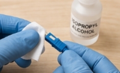
Cleaning is one of the most critical steps in fiber installation and should never be skipped.
Dust particles, even those invisible to the naked eye, can block or scatter light signals. This results in increased insertion loss and reduced performance.
Detailed cleaning process:
Apply a small amount of isopropyl alcohol to a lint-free wipe
Gently clean the ferrule end face in a single direction
Use a dry section of the wipe to remove any remaining residue
Allow the connector to air dry completely before use
In professional environments, it is recommended to follow the rule:
“Inspect → Clean → Inspect again → Connect.”
This is the gold standard for critical infrastructure like data centers, telecom central offices, and high-reliability networks.
However, in everyday practice, most technicians follow a more practical approach:
Clean → Connect. Only inspect if problems appear later. If you clean a connection and the problem persists, then it’s time to inspect. A fiber microscope will show you whether the connector is truly clean or if there is stubborn contamination, scratches, or damage that wiping cannot fix.
Step 3: Verify Compatibility
Before making any connection, ensure all components are compatible.
This includes:
Matching connector types (e.g., LC to LC, SC to SC)
Correct fiber type (single mode vs multimode)
Proper polarity alignment for duplex cables (Tx to Rx)
Incorrect matching can lead to signal failure or degraded performance. For example, connecting a multimode patch cord to a single mode system will result in significant attenuation.
Step 4: Connect the Fiber Patch Cord
When connecting the patch cord, precision and care are essential.
Hold the connector by its housing, not the cable
Align it carefully with the port to avoid misalignment
Insert gently until you feel a secure click
Never force a connector into a port, as this can damage the ferrule or internal alignment sleeve. A properly inserted connector should fit smoothly and securely without excessive pressure.
Step 5: Maintain Proper Bend Radius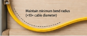
Fiber optic cables are highly sensitive to bending, which can affect signal transmission.
Each cable has a specified minimum bend radius, typically about 10 times the outer diameter of the cable. Bending beyond this limit can cause:
Increased signal attenuation
Microbending losses that are difficult to detect
Permanent structural damage to the fiber core
Always route cables using smooth curves and avoid tight corners, especially in confined installation spaces.
Step 6: Manage and Secure the Cable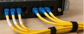
Effective cable management is essential for both performance and maintenance.
Proper management includes:
Organizing cables using trays or guides to prevent tangling
Securing cables loosely to avoid stress points
Labeling each connection for easier identification and troubleshooting
Well-managed cabling not only improves airflow and accessibility but also reduces the risk of accidental disconnections or damage during future maintenance.
Step 7: Test the Connection
After installation, testing verifies that everything is functioning correctly.
Common testing methods include:
-
Using an optical power meter to measure signal strength
How to Know Good vs Bad
| Reading | Meaning |
| Within expected range (e.g., -5 dBm to -20 dBm depending on your setup) | ✅ Good. Signal is strong enough for stable operation. |
| Too low (e.g., -30 dBm or lower than spec) | ❌ Bad. Not enough light reaching the receiver. Connection may be unstable or fail. |
| Fluctuating wildly | ❌ Bad. Loose connection, dirty connector, or damaged cable. |
In most installations, you won’t use a power meter unless you’re doing professional telecom or data center work. For office or home setups, a simple link test (step 3 below) is usually enough.
2. Performing insertion loss testing to evaluate connection quality
Is This Done in Practice?
| Environment | Is Insertion Loss Testing Done? |
| Data centers, telecom, enterprise | ✅ Yes. Required for certification and warranty. Special tools like an OLTS (Optical Loss Test Set) are used. |
| FTTH / ISP installations | ✅ Yes. Technicians use a power meter and light source to verify loss before leaving the site. |
| Small business or home office | ❌ Rarely. Most people simply plug in and check if the connection works. |
3. Checking link stability between connected devices
Link stability is simply checking whether the connection stays up and works reliably. This step ensures the connection is not just “working,” but stable over time and under real traffic conditions.
How to test:
| Method | What to Do |
| Ping test | From a computer, run ping -t (Windows) or ping continuously. Watch for dropped packets or high latency. |
| Link lights | Check the equipment port. Solid green usually means a stable connection. Flashing or no light means problems. |
| Speed test | Run a speed test to see if you’re getting expected throughput. Slow speed can indicate signal issues. |
| Transfer a large file | Copy a large file across the network. If it fails or is very slow, there’s a problem. |
| Monitor over time | Let it run for a few hours or overnight. Intermittent issues often show up over time. |
Testing ensures that any issues are identified immediately rather than after the network is put into operation, saving time and reducing downtime.
Conclusion
Fiber patch cord installation may seem straightforward, but it requires attention to detail and adherence to best practices. From cleaning connectors to maintaining proper bend radius, every step plays a role in ensuring optimal network performance.
By following the guidelines in this article, you can build a stable, high-performance fiber network with minimal signal loss and maximum reliability.
FAQ: Fiber Patch Cord Installation
Q1: Can I reuse a fiber patch cord after removal?
Yes, but it must be cleaned and inspected thoroughly before reuse to ensure performance is not compromised.
Q2: How do I know if my fiber connection is good?
You can use testing tools like an optical power meter or OTDR to measure signal strength and detect losses.
Q3: What happens if I bend a fiber cable too much?
Excessive bending can cause signal attenuation or even permanent damage to the fiber core.
Q4: Do fiber patch cords require regular maintenance?
Yes, periodic cleaning and inspection are necessary, especially in environments with dust or frequent handling.


