
-
 In the world of fiber optic connectivity, two terms often come up in discussions about network setups, installations, and infrastructure: patch cord and pigtail. Both are essential for ensuring reliable data transmission, but they serve different roles and have unique characteristics. Understanding these differences is essential, especially if you’re involved in designing or maintaining fiber optic networks. In this blog, we’ll break down what is patch cords and pigtails, explain their unique functions and common types, and help you determine which one is best for your needs. What is a Patch Cord? A patch cord, sometimes referred to as a fiber jumper or patch cable, is a brief fiber optic wire used to link devices or network components. Patch cords are typically used to link equipment such as fiber optic switches, routers, or network ports to other network devices or to provide connections within a fiber distribution panel. Key Features of Patch Cords: Pre-terminated: Patch cords come with connectors on both ends, making them ready for installation right out of the box. Variety of Connectors: They are available with various connector types, such as SC, LC, ST, MTP/MPO, or MTRJ, to suit different equipment and standards. Length:Patch cords can be installed in a variety of ways because they are available in lengths ranging from a few inches to several meters. Use Case: Primarily used to link two devices or to extend the length of a fiber optic network connection. What is a Pigtail? A fiber optic pigtail is a length of fiber optic cable that has a connector pre-attached to one end, while the other end is left unconnected or is stripped for splicing. Pigtails are designed to be spliced onto another fiber cable or a fiber optic panel to establish a continuous fiber link. Key Features of Pigtails: Single Connector: Pigtails typically…Read more →
-
 In the world of high-speed data transmission, fiber optics reign supreme. But ensuring these networks perform flawlessly requires precise tools—and one of the most critical is the optical fiber power meter. Whether you’re installing new fiber lines or troubleshooting existing ones, understanding this device is key to maintaining optimal performance. Let’s dive into what an optical power meter is and why it is important in fiber optic installation and maintenance by power meter fiber testing. What is an Optical Fiber Power Meter? One tool for determining the power level of light traveling through an optical fiber is an optical fiber power meter. In essence, it helps engineers and technicians assess the fiber optic link’s quality by measuring the light’s signal strength in microwatts (µW) or decibels (dB). These power meters are designed to work with a variety of fiber types, wavelengths, and applications, offering accurate readings to maintain network performance. In fiber optic systems, light signals travel through fiber cables. Over long distances, the light can experience attenuation (signal loss), which can degrade performance. The role of the optical fiber power meter is to measure how much light is being received at the output end of the fiber and compare it to the transmitted power level. This measurement helps detect any losses that may occur during installation, identify weak spots in the system, and verify if the signal strength meets the requirements for the application at hand. Think of it as a “health monitor” for fiber optics: just as a doctor uses a stethoscope to listen to your heartbeat, a power meter “listens” to the light signals to diagnose issues like breaks, bends, or dirty connectors. Why is an Optical Fiber Power Meter Important in Fiber Optic Installation? Ensures Accurate Installation: During fiber optic installation, an OFPM helps ensure that the fiber is…Read more →
-
 In the fast-evolving world of data centers and high-speed networking, QSFP (Quad Small Form-Factor Pluggable) transceivers play a crucial role in enabling high-bandwidth connectivity. In this comprehensive guide, we’ll explore what QSFP is, its different variants, how it works, and why it’s a game-changer for high-speed network environments. What is QSFP? QSFP (Quad Small Form-Factor Pluggable) is a compact, hot-pluggable optical transceiver used for high-speed data communication. The “Quad” in its name refers to its ability to support four channels of data transmission simultaneously, making it ideal for high-bandwidth applications like data centers, cloud computing, and telecommunications. The QSFP transceiver is designed to handle higher data rates than its predecessor, the SFP (Small Form-factor Pluggable). While SFP supports speeds up to 10G, QSFP is capable of supporting data rates from 40G to 400G, making it ideal for next-generation network infrastructure. How Does QSFP Work? A QSFP transceiver is essentially a plug-and-play component that can be inserted into compatible slots on networking devices like switches, routers, and servers. The QSFP module consists of both electrical and optical components that manage data transmission over short or long distances using fiber optic cables. Electrical Interface: The transceiver receives electrical signals from the host device and converts them into optical signals that can be transmitted over the fiber optic cable. Optical Interface: Once the electrical signals are converted to optical signals, they travel through the fiber optic medium, where they can be transmitted over longer distances at much higher speeds. QSFP modules typically come in two forms: optical transceivers (for fiber optic connections) and copper cables (for direct electrical interconnects). Depending on the type of network and desired performance, network operators can choose between different QSFP modules for their specific requirements. Types of QSFP Modules (2025 Update) As technology advances, QSFP has evolved into multiple variants to support…Read more →
-
 What is DSL (Digital Subscriber Line)? Before diving into What is VDSL, ADSL, and SHDSL , and the specifics of VDSL, ADSL, and SHDSL modem Routers, it’s important to first understand the concept of DSL (Digital Subscriber Line), as these technologies are all variations of DSL. DSL is a family of technologies used to transmit high-speed internet and data over traditional copper telephone lines. Unlike dial-up connections, which only provide basic internet access by interrupting phone service, DSL allows for simultaneous voice and data transmission. This means you can use your telephone and browse the internet at the same time without interference. DSL works by splitting the frequency range of the copper line into separate channels. One channel is used for voice communication (telephone calls), while other channels are used for high-speed internet data transmission. This division of bandwidth allows for more efficient use of the telephone line, providing much faster speeds than dial-up without requiring new infrastructure like fiber optics. There are different types of DSL technologies, each with varying speeds, distances, and applications. These include ADSL (Asymmetric DSL), VDSL (Very-high-bit-rate DSL), and SHDSL (Symmetric DSL) — all of which rely on copper telephone lines for broadband internet access. Each of these technologies has distinct characteristics that affect their performance and use cases. In this blog, we’ll break down what VDSL, ADSL, and SHDSL routers are, their functions, and the key differences between them. Whether you’re a business, consumer, or network professional, understanding these technologies can help you choose the right solution for your needs. What is VDSL (Very-high-bit-rate Digital Subscriber Line)? VDSL is an advanced version of DSL technology, offering significantly higher data transfer rates than ADSL. It uses a higher frequency spectrum to achieve faster speeds, making it suitable for applications that require large amounts of data transmission, such…Read more →
-
 In the ever-evolving world of networking, businesses and network engineers often face the challenge of integrating different types of transmission media and network standards. With the growing demand for high-speed data, reliable communication, and long-distance connections, it’s crucial to have the right tools in place. This is where media converters come in. But what exactly is a media converter, and What Does a Media Converter Do, to a more efficient, flexible, and reliable network? Understanding Media Converters: The Basics A media converter is a device that facilitates the conversion of one type of network media to another. It acts as a bridge between two different network standards, typically between fiber-optic and copper Ethernet cables, though it can also convert between other mediums such as coaxial cables and wireless connections. At its core, a media converter ethernet enables seamless communication between devices that use incompatible transmission media. It ensures that data can flow uninterrupted, regardless of the physical medium in use, thereby overcoming the limitations imposed by traditional Ethernet cables. What Does a Media Converter Do? 1. Copper to Fiber Conversion One of the most common use cases for media converters is the conversion of copper Ethernet (typically CAT5e or CAT6 cables) to fiber-optic cables (like single-mode or multi-mode fiber). This conversion allows for longer-distance data transmission without signal degradation. Ethernet cables are limited in the distance they can carry data effectively (usually around 100 meters), but fiber-optic cables can transmit data over much longer distances—up to several kilometers or even tens of kilometers—without loss of signal quality. By using a media converter, network engineers can extend their networks, ensuring high-speed data delivery over vast distances. 2. Protocol Conversion Fiber to ethernet media converter don’t just work on physical media; they also handle protocol conversion. This means they can take data from one type of…Read more →
-
 Whether you’re working from home, streaming your favorite TV show, or playing online games, a steady and fast Wi-Fi connection can make or break your online experience. One of the key features that can improve your Wi-Fi network’s performance is dual band technology. But what is wifi dual band, and why should you care? What Is WiFi Dual Band? Wi-Fi dual band pertains to routers or access points that function on two distinct frequency bands: 2.4 GHz and 5 GHz. These frequencies represent the radio waves utilized by Wi-Fi networks to facilitate communication with connected devices. 2.4 GHz Band: This band is the older and more widely utilized frequency. It has a longer range but slower speeds and is more susceptible to interference. Devices like microwaves, cordless phones, and even some baby monitors can cause interference on this frequency. 5 GHz Band: This band is faster and less congested, meaning it provides higher speeds and is less prone to interference. However, it has a shorter range compared to the 2.4 GHz band. A dual band router can broadcast on both bands simultaneously, allowing devices to connect to either frequency depending on their needs. Devices that require more bandwidth, such as streaming devices, can use the faster 5 GHz band, while devices that don’t require as much speed, such as smart thermostats or printers, can connect to the 2.4 GHz band. Why Should You Care? Now that we understand what dual band Wi-Fi is, let’s explore why it matters and how it can improve your internet experience. 1. Enhanced Performance in Densely Populated Areas The 2.4 GHz band is frequently congested due to the high number of devices utilizing this frequency. In environments such as apartments, office buildings, or other crowded spaces, numerous Wi-Fi networks compete for bandwidth on the 2.4 GHz band….Read more →
-
 In the world of high-speed fiber optic communication, optical receivers are vital for converting light signals back into electrical signals for further processing. However, the signal received at the end of a fiber optic line is often weaker than when it was transmitted, due to various forms of loss. These losses can disrupt communication, reduce data throughput, and increase error rates. Understanding the common causes of signal degradation and their respective solutions is key to maintaining a robust and efficient optical network. Below, we explore the primary issues affecting signal integrity at the optical transmitter receiver end and what can be done to prevent or fix them. Causes of Signal Loss in Optical Receivers 1. Connector and Splice Losses Connector and splice losses are among the most common causes of signal attenuation in optical fiber systems. Every point where two fibers are joined—either via connectors or splicing—presents an opportunity for light to scatter or reflect due to misalignment, poor polishing, or contamination. Even slight imperfections at these joints can cause insertion loss, which adds up across long-distance links or complex networks. The Solution: Use high-performance connectors like angled physical contact (APC) connectors, which reduce back reflection better than flat or ultra-polished connectors. Fusion splicing is preferable over mechanical splicing due to its superior alignment precision and lower insertion loss (typically <0.1 dB). Perform connector inspection and cleaning using dedicated tools like a fiber scope and non-abrasive cleaning swabs before every connection. Test splices with an Optical Time Domain Reflectometer (OTDR) to verify quality after installation. 2. Fiber Bending Loss Fiber bending loss occurs when an optical fiber is bent beyond its physical tolerance, causing light to escape from the core. This can be particularly problematic in confined spaces, dense cabling environments, or installations with improper cable management. The tighter the…Read more →
-
 If you’re building a home theater setup or trying to improve your TV’s sound quality, chances are you’ve come across something called optical audio. It’s not as commonly discussed as HDMI, but it’s a powerful and reliable way to connect your audio gear—and it’s still very much in use today. In this blog, we’ll explain what optical audio is, how optical input and output ports work on your TV and sound system, and the role of an optical receiver in delivering high-quality audio. 🔍 What is Optical Audio? Optical audio, also known as TOSLINK (short for Toshiba Link), is a technology that uses light signals sent through fiber optic cables to transmit digital audio from one device to another. Instead of sending electrical signals like traditional audio cables, optical cables use pulses of light to carry the sound data. Key Advantages: ✅ No interference: Since it uses light, it’s immune to electrical interference from nearby devices. ✅ Supports surround sound: Optical can transmit formats like Dolby Digital and DTS (up to 5.1 channels). ✅ Reliable connection: Great for consistent audio quality over long periods. Limitations: ❌ Doesn’t support advanced formats like Dolby TrueHD or DTS:X. ❌ Audio only – Unlike HDMI, optical cables do not transmit video. 📺 What is an Optical Output on a TV? The optical output on your TV is a port designed to send digital audio from the TV to an external device like a soundbar, home theater system, or AV receiver. How to Identify It: Look for a small square-shaped port on the back or side of your TV, often labeled: “Digital Audio Out (Optical)” “SPDIF” “TOSLINK” When active, you might see a faint red laser light inside. How It Works: When your TV plays content—whether it’s cable, streaming, or gaming—the optical output sends that audio signal via light pulses through a fiber optic cable to a receiving device….Read more →
-
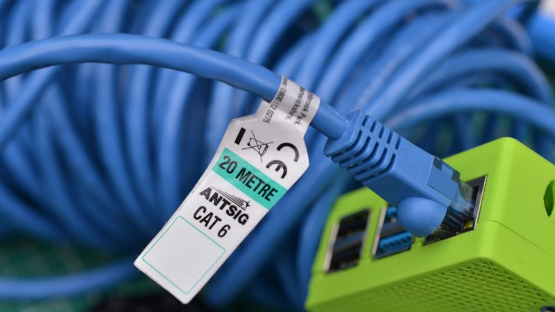 What Is a CAT Cable? “CAT” stands for Category, and CAT cables are standardized twisted-pair cables used for Ethernet and other network physical layers. Each new category typically improves on the last in terms of speed, frequency, and shielding. Whether you’re setting up a home office, optimizing your gaming setup, or just trying to improve your internet speed, choosing the right Ethernet cable can make a big difference. With all the different “CAT” (category) cable type out there—CAT5e, CAT6, CAT6a, CAT7, CAT8—it’s easy to feel overwhelmed. This cable buying guide breaks Best CAT cable all down so you can find the perfect standard Ethernet cable for your needs. Types of CAT Cables (With Detailed Breakdown) Category Speed Bandwidth Shielding Max Length Use Cases CAT5e 1 Gbps 100 MHz Unshielded 100 m Basic networking CAT6 1 Gbps 250 MHz Shielded or Unshielded 100 m Home and office networks CAT6a 10 Gbps 500 MHz Shielded or Unshielded 100 m Commercial networks CAT7 10 Gbps 600 MHz Shielded 100 m Data centers CAT8 25–40 Gbps 2000 MHz Shielded 30 m Data centers CAT5e (Category 5 Enhanced) Speed: Supports up to 1 Gbps (Gigabit Ethernet). Bandwidth: 100 MHz, enough for general internet usage. Length: Maintains performance over distances up to 100 meters (328 feet). Best For: Streaming HD video, video calls, basic gaming, general web use. Why Choose It? It’s affordable and widely available. Great for homes with 100–200 Mbps internet plans. Limitations: Not ideal for ultra-fast transfers or networks with many devices. 🔵 CAT6 (Category 6) Speed: Handles 10 Gbps, but only up to 55 meters; beyond that, it drops to 1 Gbps. Bandwidth: 250 MHz, double that of CAT5e, allowing better performance with multiple simultaneous users. Length: Works up to 100 meters for 1 Gbps; for 10 Gbps, keep it under 55 meters. Best For: Gaming, video editing, transferring large files, smart homes….Read more →
-
 In the digital age, where every device from your phone to your fridge can connect to the internet, securing and managing your network is more important than ever. Two essential tools in this process are routers and firewalls. While they may seem similar—or even come bundled in a single device—they serve very different purposes. Let’s break down Router vs. Firewall what they do, what is their Key Function, what is router and firewall difference, and when to use each one. What Is a Router? A router is a networking device that forwards data packets between different computer networks. In simpler terms, it’s the device that connects your home or office network to the internet. Key Functions of a Router: Traffic Direction (Routing Data): Routers determine the most efficient path for data to travel from your device (like your laptop or smartphone) to its destination (like a website or server) and back again. They make real-time decisions to ensure that data flows quickly and reliably. Network Segmentation: Routers can create multiple logical networks within a single physical network. For example, they can separate a “Guest” Wi-Fi network from your main home network to prevent guests from accessing your personal devices. IP Address Assignment (DHCP Server): Most routers automatically assign unique IP addresses to each connected device using a feature called DHCP (Dynamic Host Configuration Protocol). This prevents address conflicts and simplifies network management. Basic Security Features (NAT and SPI): Routers typically include basic protection features like Network Address Translation (NAT), which hides your internal IP addresses from external networks, and Stateful Packet Inspection (SPI), which inspects data packets to allow only legitimate traffic. What Is a Firewall? A firewall is a network security device—or software—that monitors, filters, and controls incoming and outgoing network traffic based on pre-defined security rules. Its main job is…Read more →
-
 When setting up a network, it’s easy to focus solely on speed and forget a key element of performance: cable shielding. Whether you’re wiring a home office or planning a full enterprise setup, understanding the difference between UTP, FTP, and STP cables — especially in CAT5e and CAT6 standards — is crucial for network reliability and interference protection. Let’s break it down. What Is Cable Shielding? Shielding refers to protective layers within Ethernet cables that guard against electromagnetic interference (EMI) and crosstalk. EMI can come from nearby power cables, fluorescent lights, industrial equipment, or even neighboring Ethernet cables. The goal of shielding is to maintain signal integrity and data transmission quality. The Key Players: UTP, FTP, and STP When it comes to Ethernet cables, the type of shielding significantly influences performance, especially in electrically noisy environments. Let’s dive into the three primary types of cable shielding used in CAT5e and CAT6 cables. 1. UTP (Unshielded Twisted Pair) Construction: UTP cables contain four pairs of twisted copper wires, with no additional shielding. The twisting helps reduce crosstalk (interference between wire pairs), but there’s no extra layer to protect against external noise. Advantages: Most affordable and flexible option Easier to install, especially in tight spaces or for long cable runs Ideal for most standard office or residential networking needs Limitations: Susceptible to external electromagnetic interference (EMI) from nearby power lines, fluorescent lighting, or large electronic equipment Typical Applications: Home networking, basic office setups, VoIP systems, and areas with minimal EMI. 2. FTP (Foiled Twisted Pair) Construction: FTP cables have an overall foil shield wrapped around all four twisted pairs, providing a layer of protection against EMI. Advantages: Offers better EMI protection compared to UTP Reduces alien crosstalk (interference from adjacent cables) Suitable for environments with moderate EMI, such as near power…Read more →
-
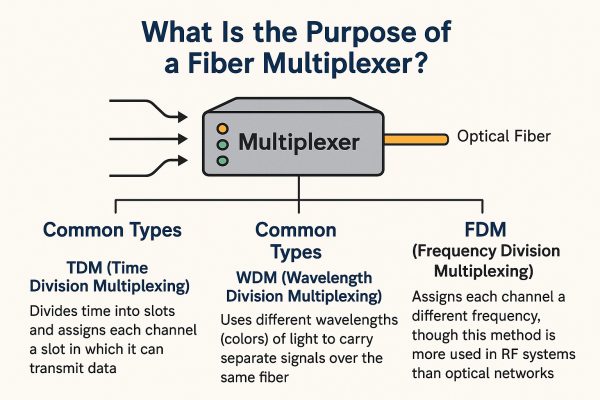 In the rapidly evolving world of networking and telecommunications, efficient data transmission is more crucial than ever. As demand for high-speed internet, seamless communication, and large-scale data transfer grows, so does the need for infrastructure that can support it. Enter the optical fiber multiplexer — what is the purpose of a multiplexer? a silent hero in the background of modern connectivity. But what exactly is a fiber multiplexer, and why is it so important? Understanding the Basics A fiber multiplexer is a device that combines multiple data signals into a single optical fiber. It works by taking input from several sources and transmitting it over one fiber line, then separating those signals at the receiving end. Think of an optical fiber like a super-fast highway that can move massive amounts of information. But instead of cars, it’s carrying data — emails, videos, phone calls, and more. Now, imagine you have 10 smaller roads full of traffic (data from different sources) that all need to get onto that main highway. You don’t want to build 10 separate highways — that would be super expensive and take up way too much space. Instead, you build a smart on-ramp that merges all the traffic in an organized way. That’s exactly what a fiber multiplexer does. It combines multiple data streams and sends them down one single optical fiber — clean, efficient, and lightning-fast. Real-World Example Suppose a metro telecom operator wants to increase backbone capacity between two city data centers. Without multiplexing, they might need to install 10 separate fiber cables, each carrying 10 Gbps. By deploying a DWDM fiber multiplexer supporting 16 wavelengths, each at 10 Gbps, they can carry 160 Gbps over just one fiber strand. That reduces physical infrastructure costs (cabling, conduit, trenching) by up to 90%, simplifies maintenance, and leaves room for…Read more →
-
 In today’s high-speed digital era, fiber optic networks power everything from 5G telecom to cloud computing. Yet, these cables are vulnerable to dust, bends, and faulty splices—making precise fiber optic testing non-negotiable for network reliability. This comprehensive fiber optic cable tester kit guide demystifies fiber optic testing tools, their applications, and best practices for accurate results. Plus: Get our scenario-based tool selection checklist! In this blog, we’ll walk through the most common fiber optic cable testing tools, explain what they do, show you how to use them effectively for accurate, reliable results, and offer you a super detailed usage scenario guide. Why Fiber Tester kit Matters Fiber optic cables transmit data using light, which makes them fast and efficient—but also sensitive to dust, bends, splices, and poor connections. Testing ensures: Proper signal strength Minimal loss or interference Network reliability Compliance with industry standards (like TIA/EIA or ISO) 5 Essential Fiber Optic Testing Tools (With Step-by-Step Guides) 1. Visual Fault Locator (VFL) What it does: A VFL sends a visible red laser light through the fiber. Breaks, bends, or faults will cause the light to escape the fiber, making the issue easy to spot. How to use: Connect the VFL to one end of the fiber using the correct adapter. Turn on the laser. Visually inspect the cable along its length—look for bright red light leaking from faults or breaks. 2. Optical Power Meter (OPM) and Light Source (LS) What they do: These work as a pair. The light source sends a specific wavelength of light through the fiber. The power meter measures how much light arrives at the other end, helping calculate insertion loss. How to use: Connect the light source to one end of the fiber. Connect the optical power meter to the other end. Turn both on and ensure they…Read more →
-
In today’s industrial landscape, reliable and efficient networking solutions are crucial for ensuring seamless operations. One such solution is the PoE industrial switch. This powerful Ethernet switch with PoE device not only facilitates data communication but also provides electrical power to connected devices, making it a popular choice for industrial environments. What is a PoE Industrial Switch? A PoE (Power over Ethernet) industrial switch is a network switch designed specifically for rugged and harsh environments. It integrates PoE technology, which allows both data and electrical power to be transmitted over a single Ethernet cable. This eliminates the need for separate power sources, reducing installation complexity and costs. How Does a it Work? A PoE industrial switch integrates Power over Ethernet technology, allowing network cables to carry electrical power alongside data. This is particularly useful for powering devices like: ✔ IP cameras ✔ Wireless access points ✔ IoT sensors ✔ Industrial automation equipment By doing so, it simplifies network design and reduces the number of cables required, making it an ideal solution for rugged industrial settings. Unlike commercial switches, these devices are engineered for reliability in environments like factories, oil rigs, or outdoor installations. Key Features of PoE Industrial Switches Power and Data Transmission: PoE switches can deliver power and data to devices such as IP cameras, wireless access points, and IoT sensors using a single Ethernet cable. Rugged Design: These switches are built to withstand extreme temperatures, humidity, vibration, and electromagnetic interference. High Reliability: With features like redundant power inputs and industrial-grade components, PoE industrial switches ensure stable network performance. Scalability: Many models offer multiple ports and advanced networking features, making them suitable for large-scale industrial applications. Smart Management: Managed PoE industrial switches provide remote monitoring, power scheduling, and network diagnostics. Applications of PoE Industrial Switches PoE industrial switches are widely used in various industries,…Read more →
-
Industrial Ethernet switches play a vital role in ensuring reliable connectivity across factories, smart grids, transportation, and other mission-critical environments. When choosing a switch, the key question often arises: should you use a managed industrial switch or an unmanaged industrial switch? This guide explains the differences, benefits, and applications of each type, helping you make the right choice for your industrial network. What Are Industrial Switches? Before we compare managed and unmanaged, it’s important to understand what makes any switch “industrial.” Unlike office-grade switches, industrial switches are built to withstand harsh environments. They are housed in robust, metal casings and designed to operate reliably in extreme conditions, including: Wide Temperature Ranges: They can function in freezing cold (e.g., -40°C) and scorching heat (e.g., 75°C) where standard commercial switches would fail. Dust, Moisture, and Vibration: They feature high Ingress Protection (IP) ratings (like IP40 or IP67) that guarantee resistance against dust and water. They are also built to resist constant vibration from heavy machinery. Electrical Noise: Industrial settings are filled with electromagnetic interference (EMI) from large motors and equipment. Industrial switches have superior shielding to maintain a stable connection amidst this electrical noise. Redundant Power Inputs: Many feature dual DC power inputs to ensure continuous operation even if one power source fails. Whether managed or unmanaged, these rugged characteristics are non-negotiable for any network device deployed on the factory floor, in a wastewater treatment plant, or alongside a railway. Unmanaged Industrial Switches: Simple & Cost-Effective An unmanaged industrial switch is a simple, straightforward device. Think of it as a robust, industrial-strength version of the simple network switch you might use at home. Its primary job is to take data packets coming in from one port and automatically forward them to the correct destination port so that devices can communicate. It does…Read more →
Testimonials

Lomoveishiy – Finland11

