
-
 1. Introduction Optical fiber is a technology that uses very thin strands of glass or plastic to send data using light signals. It’s used in everything from home internet to large telecom networks. If you’re just starting to learn about fiber optics, you might come across four common terms: single fiber vs dual fiber, single mode vs multimode fibre. These terms can sound similar, but they actually describe different things: Single-mode vs. multimode refers to the type of fiber core and how light travels inside it. Single-fiber vs. dual-fiber refers to how many fiber strands are used to send and receive data. In this guide, we’ll explain each of these clearly and simply so you can understand their differences,know when to use each one and solve confusing problem: is single mode fiber bidirectional? Can single-mode fiber work with a multimode SFP? 2. Single-Mode vs. Multimode Fiber What is Single-Mode Fiber? Single-mode fiber has a very small core—about 8 to 10 microns wide. It allows just one wavelength mode laser to travel through it. Because the laser moves in a single line, the signal stays clear over very long distances. What is Multimode Fiber? Multimode fiber has a larger core, usually 50 or 62.5 microns. This allows many one wavelength mode laser to travel at the same time through one paths. While this makes it easier to use and cheaper for short distances, it causes signal spreading (called modal dispersion), which weakens the signal over longer distances. 3. Single-Fiber vs. Dual-Fiber What is Single-Fiber? Single-fiber systems use one fiber strand for both sending and receiving data. This is done using different wavelengths (colors of light) for each direction. This method is useful in places where space is limited or when reducing fiber usage is important. What is Dual-Fiber? Dual-fiber systems use two separate fiber strands—one for sending data and one for…Read more →
-
Modern communication networks are built on fiber optic cables. They provide incredibly dependable and quick communications by using light to carry data. When choosing a fiber optic cable for your network, What are the two main types of fiber optic cable and uses? you will mostly come across two main types: single mode fiber and multimode fiber. These are the most common types of fiber optic cable, and each is designed for different situations. Understanding single mode and multimode fiber difference and how they are used will help you make better choices for your home, business, or industrial network. What Are the Two Main Types of Fiber Optic Cable? The two main types of fiber optic cables are single mode and multimode. The main difference between them lies in the size of their core and how they carry light. The core is the center of the fiber where the light travels. Only one path, or mode, of light can flow straight down a single mode fiber due to its extremely small core, which is only 9 microns wide. On the other hand, multimode fiber can carry many light channels simultaneously due to its thicker core, which is between 50 and 62.5 microns diameter. This core size difference affects how far and how fast the data can travel. What Is Single Mode Fiber (SMF)? Single-Mode Fiber has a very skinny core, only about 9 micrometers wide (that’s thinner than a human hair!). Because it’s so narrow, light can only travel straight down the center in a single, direct path – like a laser beam shooting straight ahead. This simple path means the light signal stays strong and doesn’t get messed up, even over incredibly long distances. Think hundreds of kilometers! To make this work, Single-Mode uses powerful laser light sources. You’ll often see these cables with a yellow outer jacket. Because light travels so cleanly in one mode, Single-Mode Fiber offers the highest possible speeds and the longest distances. It’s the go-to choice for massive networks: long-distance phone lines and internet backbones (like cables under the ocean connecting continents), cable TV company main…Read more →
-
Splicing optical fibers is a common task in building and repairing fiber optic networks. It helps connect two fiber cables to make one continuous link. But what if the two fibers have different core sizes? Can you still splice them together using fiber fusion splicer? The short answer is yes, but there are some important things to know. The type of fibers you are working with matters a lot. In general, there are two main situations: A. Splicing Between Single-Mode and Multimode Fibers B. Splicing Between Same-Mode Fibers with Different Core Sizes Each case has its own challenges and solutions, which we’ll explain below. Understanding Fiber Core Types Optical fibers have a center part called the core, where light travels. The size of this core and the way light moves inside it affect how the fiber works. Single-mode fiber (SMF) has a very thin core, about 8 to 10 microns wide. It carries only one path of light and is used for long distances, like connecting cities or large buildings. Multimode fiber (MMF) has a wider core, usually 50 or 62.5 microns wide. It carries several light paths and is used for short distances, like inside offices or data centers. If you try to splice fibers with different core sizes or types, light may not flow smoothly, which can cause signal loss or poor performance. A. Splicing Between Single-Mode and Multimode Fibers Using fiber fusion splicer to Splicing a single-mode fiber to a multimode fiber is not recommended, but sometimes it has to be done. The problem is that these fibers work in very different ways. Single-mode fiber sends light in one straight path, while multimode fiber sends light in many paths. Also, the core sizes are very different. This causes several problems. Challenges First, a lot of the light may get lost…Read more →
-
 Fiber optic cables are widely used in modern communication systems because they can carry data at high speed over long distances. But sometimes, during installation or repair, these cables need to be connected or fixed. This process is called fiber optic splicing. Splicing helps link two optical fibers so light can continue traveling with minimal signal loss. There are the two types of fiber optics splicing : fusion splicing and mechanical splicing. Each method has its own use, tools, and benefits. In this article, we will focus on mechanical splicing, which is a simple and effective way to splicing fiber optic cable without machine. The Two Types of Fiber Optic Splicing Before diving deeper into mechanical splicing, it’s helpful to understand the two basic types of fiber splicing used in the field: 1. Fusion Splicing Fusion splicing uses a special machine to align and melt two fiber ends together using an electric arc. The result is a very strong and permanent connection with extremely low signal loss—usually less than 0.1 dB. Fusion splicing is best for long-term, high-performance applications such as backbone networks, internet infrastructure, and outdoor cable installations. However, it requires expensive equipment and trained technicians. 2. Mechanical Splicing: Splicing Fiber Optic Cable Without Machine Mechanical splicing does not use heat. Instead, it joins the two fibers by holding them in place inside a small connector or sleeve. A gel with similar optical properties is sometimes used to improve signal transmission. This method is quick, cost-effective, and ideal for emergency repairs, testing, or situations where a fusion splicer is not available. Both methods are useful, depending on the job. But if you’re working in the field, on a budget, or need a fast solution, mechanical splicing is the best choice—and it’s the main topic of this guide. What Is…Read more →
-
 As fiber optic networks continue to expand across enterprises, data centers, and telecom infrastructures, choosing the right optical transceiver is crucial for ensuring high performance and cost efficiency. Two common types of transceivers are SFP BiDi (Bidirectional) and SFP Duplex in networking. While both are designed for transmitting data over fiber optic cables, SFP bidi vs duplex differ significantly in how they operate and are deployed. In this article, we break down What Is an SFP BiDi Module and SFP Duplex Module? SFP BiDi vs Duplex When Should You Use SFP BiDi and When Should You Use SFP Duplex? to help you decide which module is best for your network. What Is an SFP BiDi Module? SFP BiDi (Bidirectional Small Form-Factor Pluggable) modules are a type of optical transceiver that use a single optical fiber to both transmit and receive data. This is achieved using Wavelength Division Multiplexing (WDM), a technology that allows multiple wavelengths of light to travel in both directions simultaneously on the same fiber strand. Each SFP BiDi module contains two separate optical components—one that transmits data (Tx) at a specific wavelength (such as 1310 nm) and one that receives data (Rx) at a different wavelength (such as 1550 nm). Because the transmitting and receiving functions operate on separate wavelengths, both directions of communication can be handled over a single strand of fiber. However, it is essential to use SFP BiDi modules in complementary pairs; for instance, one end must transmit at 1310 nm and receive at 1550 nm, while the other end must do the reverse. Further reading: What Is a BiDi SFP? Understanding Bidirectional Optical Transceivers What Is an SFP Duplex Module? SFP Duplex modules, also known as standard or full-duplex SFPs, are the most commonly deployed optical transceivers in fiber optic networks. These modules require…Read more →
-
VFL (visual fault locator) are indispensable tools in fiber optic network maintenance. They provide a quick and cost-effective way to detect faults, bends, breaks, or poor connections in optical fibers. However, how to use a visual fault locator is simple; many technicians—especially those new to fiber optics—often make critical errors during testing that can lead to misdiagnosis, network inefficiencies, or even safety hazards. In this blog, we’ll explore the most common mistakes to avoid when using a VFL to test fiber optic cables, and how to ensure accurate and safe testing every time. Preparation of Fiber testing 1. Using a VFL on Active Fiber Links Mistake: Applying a VFL to a live fiber that is presently transmitting data signals Why It’s a Problem: VFLs typically use red laser light at 650nm, which does not combine well with the wavelengths used for data transmission (typically 1310nm, 1490nm, or 1550nm). Applying a VFL to a live system can not only interfere with data transmission but may also damage active optical equipment. Solution: Always disconnect the fiber from live equipment before connecting the VFL. Verify that the link is inactive and safe for testing. 2. Improper Connector Cleaning Mistake: Connecting a VFL to a dirty fiber optic connector. Why It’s a Problem: Dirt or debris on the connector can scatter or block the laser light, resulting in misleading results. In some cases, it may even damage the VFL’s output port. Solution: Clean all fiber connectors with approved cleaning tools and solutions before testing. 3. Exceeding Recommended Length Limits Mistake: Using a VFL on long-distance links beyond its effective range. Why It’s a Problem: VFLs are designed for short-range fault location (typically up to 5 km). Beyond this range, the laser light attenuates and may not be visible even if a break exists, leading to false assumptions that the link is fault-free. Solution: Use VFLs only for short-distance troubleshooting. For longer links,…Read more →
-
 In this article, we’ll explore what does VFL stand for, what OTDR is in optical fiber, and the key differences between VFL and OTDR and focus on when and why a Visual Fault Locator is the right tool for the job. What Is a Visual Fault Locator (VFL)? A Visual Fault Locator is a compact, handheld device that emits a bright red laser (typically 650 nm) through the fiber. The light travels through the core of the optical fiber and visibly escapes at breakpoints, sharp bends, faulty connectors, or cracks. Because the light is visible to the human eye, faults can be quickly located by simply inspecting the fiber for red light leakage. Read more: What is VFI in Fiber Optics and How to Use It What Is an OTDR? An Optical Time-Domain Reflectometer (OTDR) sends a series of optical pulses into the fiber and measures the backscattered and reflected light to create a trace—a graphical representation of the fiber’s condition over distance. OTDRs are sophisticated instruments capable of detecting and analyzing splices, bends, connector losses, and fiber breaks along many kilometers. Read more: What Is OTDR? VFL vs OTDR: A Comparative Snapshot Feature VFL OTDR Fault Detection Range Up to 30 km (short links) 200 km (long links) Type of Faults Visual breaks, bends, misaligned connectors Splice loss, attenuation, reflection, fiber length Ease of Use Plug-and-play, no setup required Requires configuration and analysis Cost Low High Portability Extremely portable Larger and heavier Best Use Case Quick checks, short links, field work Full certification, long-haul fiber, detailed analysis When and Why to Use a Visual Fault Locator (VFL) A Visual Fault Locator is especially valuable in scenarios that require quick, on-the-spot diagnostics for short fiber links. For instance, in last-mile fiber deployments such as Fiber to the Home (FTTH) or in-building…Read more →
-
 In fiber optic networks, efficient troubleshooting tools are essential for minimizing downtime and ensuring signal integrity. One such indispensable tool is the Visual Fault Identifier (VFI). Understanding what a VFI meaning is and how to use it properly can save time, effort, and money. Note: VFI (Visual Fault Identifier) is also known as VFL (Visual Fault Locator). Both terms describe the same tool used to detect faults in fiber optic cables by emitting visible red light. What is a VFI (Visual Fault Identifier)? A Visual Fault Identifier (VFI) is a compact and cost-effective tool used to visually locate faults in fiber optic cables. It emits a bright red laser light—typically at a wavelength of 650 nm—that travels through the fiber core.When the fiber is intact and functioning properly, the light remains contained within the cable. However, if there is a physical break, severe bend, poor splice, or damaged connector, the red light will leak out or scatter at the fault location, making it easy to pinpoint the issue by eye. VFIs are especially useful in the field due to their simplicity, portability, and quick results. Depending on the output power—typically ranging from 1 mW to 30 mW—a VFI can trace faults over distances of up to 3 to 30 kilometers in single-mode fibers. Many models support both continuous wave (CW) mode for steady illumination and pulse mode, which helps detect light leakage more easily in certain conditions. VFIs are usually equipped with standard optical connector interfaces such as SC, FC, or ST How Does a VFI Work? The VFI operates by injecting a visible red laser into one end of a fiber optic cable. Optical fibers guide light through total internal reflection, meaning the light is supposed to stay confined within the core. If the fiber is damaged or improperly spliced, the laser beam…Read more →
-
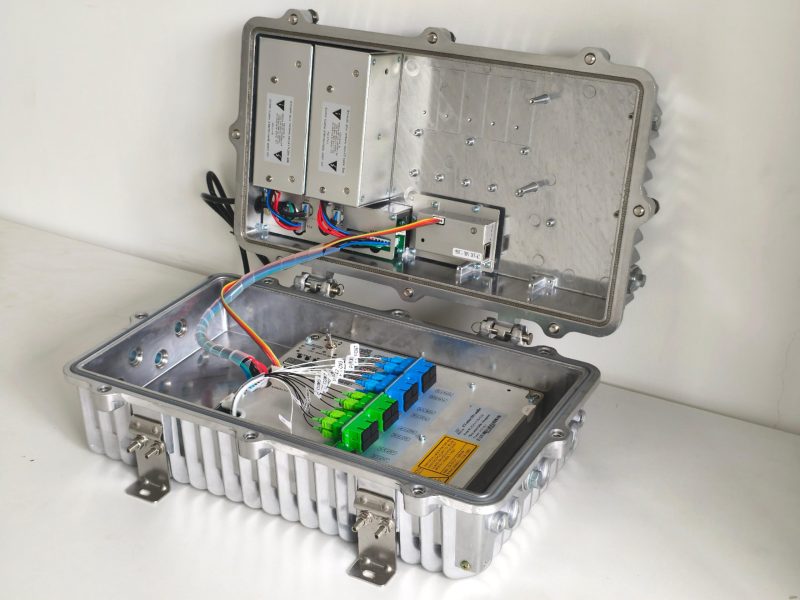 Shanghai, China – 2025.5.12 – Baudcom, a leading global provider of advanced fiber optic communication solutions, is proud to announce the launch of its latest innovation: the 8-Port Outdoor EDFA (Erbium-Doped Fiber Amplifier) with integrated WDM technology. Designed to meet the growing demands of modern FTTx and PON networks, this new model provides unmatched performance, reliability, and scalability for GPON and XPON OLT deployments in outdoor environments. Powerful Optical Amplification with Smart WDM Integration The newly released EDFA stands out with its 8 high-power output ports, allowing service providers to amplify and distribute optical signals across multiple fiber routes without additional splitters. Each port delivers a stable +17 dBm output, supporting long-distance transmission and high split ratios—ideal for rural, suburban, or densely populated FTTH rollouts. What truly sets this model apart is its built-in WDM functionality, enabling seamless upstream and downstream wavelength multiplexing (1310 nm, 1490 nm, 1550 nm) over a single fiber. This feature allows direct connection to GPON/XPON OLTs, simplifying the network architecture and reducing passive component costs. Designed for Outdoor Durability and Uptime Baudcom’s 8-Port Outdoor EDFA is enclosed in a robust IP66-rated housing, engineered to withstand harsh weather conditions, temperature extremes from –40 °C to +65 °C, and corrosive environments. Its compact, wall- or pole-mountable design makes it ideal for field cabinets, tower sites, or remote distribution points. To further ensure network resilience, the amplifier is equipped with dual redundant power supply modules. These operate in a hot-standby configuration, automatically switching to backup power in the event of failure—eliminating single points of failure and maximizing uptime. Smart Management and Monitoring The amplifier supports multiple management protocols, including SNMP v2/v3, RS-485, and RS-232, along with an intuitive front-panel LCD. Network operators can monitor optical power levels, temperature, alarms, and other parameters remotely, improving operational efficiency and reducing maintenance time….Read more →
-
 Imagine you’re running a bustling data center—or perhaps you’re the IT manager for a growing enterprise—and your fiber‐optic cabling runs under tight ceilings, behind walls, or through conduits where every extra strand drives up cost and installation headaches. What if you could cut that fiber count in half, simplify your network layout, and still get the same blazing‐fast performance? That’s exactly where BiDi SFPs (Bidirectional Small Form-Factor Pluggables) shine. In this post, we’ll uncover: What a BiDi SFP Meaning is How it carries signals in both directions over a single fiber Why it matters for your network’s cost, complexity, and scalability Where you’ll see it most often deployed 1. The Challenge of “Two Fibers per Link” Traditional fiber-optic links use duplex SFPs: one fiber for transmit (TX) and one fiber for receive (RX). For a single point-to-point link, you need two strands; for a 24-port switch, that’s 48 fibers snaking through trays and patch panels. Problems include: Higher Installation Costs Doubling the fiber means more cable, more splicing, and more labor. In long-distance or large-scale deployments, this can add up quickly. Limited Conduit Space Data centers and buildings often have cramped ducts and conduits. Fitting more fiber may require expensive infrastructure upgrades. Complex Maintenance Two fibers per link means more potential failure points, especially in harsh or outdoor environments. Scalability Issues As your network grows, doubling the fiber for every new link can be a limiting factor. Wouldn’t it be nice if you could do the same job with just one fiber? Enter the BiDi SFP. 2. What Is a BiDi SFP? A BiDi SFP is a specialized transceiver that uses wavelength division multiplexing (WDM) to send and receive signals over a single strand of single-mode fiber. It transmits dual wavelengths on one wavelength (e.g., 1310 nm) and receives on another (e.g., 1490 nm). You deploy a matching BiDi…Read more →
-
 Among the innovations in fiber optics, Bidirectional (BiDi) SFP modules stand out for their ability to transmit and receive signals over a single fiber strand, rather than the traditional dual-fiber setup. While this seems like a clear win in terms of cost and infrastructure efficiency, BiDi SFPs are not as widely adopted as one might expect. So, why isn’t more fiber bidirectional? In this post, we’ll explore what bidirectional really means, and the disadvantages and limitations of bidirectional SFP that network engineers must consider. What Are Bidirectional SFP Modules? In fiber optics, Understand What Does Bidirectional Mean Firstly, bidirectional refers to the ability to transmit and receive data over the same fiber strand but in opposite directions. This is achieved using Wavelength Division Multiplexing (WDM), where each direction uses a different wavelength of light to avoid interference. Bidirectional SFP (BiDi SFP) modules are compact optical transceivers that take advantage of this technology. By using just one strand of fiber instead of two, BiDi modules offer a more efficient solution for environments with limited fiber infrastructure. Before diving into the limitations, it’s important to recognize the advantages: With only one fiber strand needed, infrastructure costs can be cut in half. Less fiber means less complexity, especially in dense environments like data centers or FTTH deployments. Learn more advantages in another article. Key Limitation of Bidirectional SFP Modules Despite these advantages, bidirectional SFP come with several disadvantages that restrict their broader adoption. Higher SFP Module Price BiDi SFPs typically cost more per unit than standard duplex SFPs due to the integrated WDM filters and more complex optics. Over small-scale or short-reach deployments, the cost savings on fiber may not offset the premium on transceivers. However, with the development of optical device technology, the cost of 1.25G bidirectional transceivers is almost the same as that of dual-fiber ones,…Read more →
-
 In the high-speed world of fiber optic communication, where milliseconds matter and reliability is non-negotiable, the unsung heroes behind the scenes are fiber optic splicer. These technicians work with microscopic precision to ensure every fiber link is flawlessly connected, forming the backbone of global internet, telecommunication, and enterprise networks. But what exactly does a fiber splicer do? And what does a typical day look like for someone whose job is to turn “split ends” into seamless signals? Morning: Prepping for the Field A fiber splicer’s day often begins early. Whether they’re working on a new FTTH (Fiber to the Home) rollout or repairing damage after a storm, preparation is key. Their van is typically loaded with: Fusion Splicer machine Fiber cleavers and strippers OTDRs (Optical Time-Domain Reflectometers) Cleaning kits and protective sleeves Safety equipment and worksite signage At the start of the shift, splicers review work orders and fiber routing diagrams. In large-scale installations, they may be coordinating with network engineers or construction crews. Accuracy in planning avoids costly signal loss or downtime later. Midday: The Precision Work Begins Once on site, the real craftsmanship begins. Fiber splicers often work in utility cabinets, aerial enclosures, or underground vaults—sometimes in cramped, dusty, or poorly lit environments. Every fiber must be: Cleaned meticulously– even a speck of dust can compromise the splice. Stripped and cleaved– to expose the core with minimal loss. Fusedusing high-precision arc welding – aligning cores to within microns. Fusion splicing offers the lowest insertion loss and reflection, making it the go-to technique for long-haul and high-speed networks. Once the splice is complete, the fiber is tested using an OTDR to ensure minimal signal loss and then protected with a heat-shrink sleeve. Afternoon: Testing, Troubleshooting, and Documentation Testing is not optional—every splice must meet strict industry performance standards. If…Read more →
-
 In the world of fiber optic communication, ensuring the integrity and organization of fiber connections is paramount to achieving high performance and long-term reliability. One essential component that plays a critical role in this process is the fiber splice tray enclosure. But What Is the Purpose of Splice Trays Inside Splice Closures, and why is it so vital? What is Splice Tray? Before diving into the function of splice trays, it’s important to understand the context in which they are used. A splice closure is a protective enclosure used to house and protect optical fiber splices from environmental damage, such as moisture, dust, temperature fluctuations, and mechanical stress. These fiber splice tray enclosure are commonly deployed in aerial, underground, or direct-buried applications to maintain network continuity and minimize signal loss. Within each splice closure, you will find splice trays—modular components specifically designed to efficiently organize and safeguard fiber splices. The Primary Purposes of Splice Trays 1. Protection of Fiber Splices The primary function of a splice tray is to ensure the protection of both fusion and mechanical splices. Fiber splices are delicate connections, and exposure to physical stress or contaminants can degrade signal performance. The tray provides a stable, enclosed compartment that shields each splice from vibration, bending, and other mechanical impacts. 2. Efficient Fiber Management These trays facilitate a well-structured arrangement of fiber optic cables and splices, promoting optimal organization. Each tray holds a designated number of fibers, ensuring that the layout is logical and easy to manage. This reduces the risk of accidental damage during installation or maintenance and makes it easier to identify and access specific fibers. 3. Minimizing Signal Loss Properly organized splices and fibers mean better control of bend radius and reduced risk of microbends or macrobends, which can lead to signal attenuation. The tray’s design…Read more →
-
 In fiber optic networks, maintaining continuity, protection, and performance is essential. One critical component that enables this is the fiber optic splice closure—a rugged, sealed enclosure designed to protect fiber splices from environmental and mechanical damage. But where exactly are splice closures used, and why are they so vital across different network types? In this blog, we explore in what applications is a splice closure used, helping you understand their roles across various industries and deployment scenarios. What is a fiber optic splicer? Before diving into the applications, let’s briefly recap what a splice closure does. A splice closure provides a secure and protective environment for fiber splices, ensuring the fiber remains aligned, undamaged, and shielded from moisture, dust, and mechanical stress. Most closures support multiple cable entry points and can be used in aerial, duct, direct-buried, or pole-mounted setups. Read more click here: What is Fiber Optic Splicer Closure? Key Applications of Splice Closures 1. FTTH (Fiber to the Home) Networks Splice closures are a cornerstone in FTTH deployments, especially in the distribution and drop sections of the network. They enable splicing of feeder cables to distribution cables or drop fibers, often housed in outdoor cabinets, aerial closures, or wall-mounted units. Why it matters: Reliable fiber splicing ensures uninterrupted high-speed internet for residential users. 2. Backbone and Long-Haul Networks In core and long-distance fiber networks, splice closures are used to join large-capacity trunk cables during installation or maintenance. These closures must withstand extreme weather and physical stress, especially when buried or installed along railways and highways. Why it matters: Backbone networks demand minimal signal loss and high reliability over long distances. 3. Metro and Access Networks Splice closures serve a critical role in metro ring and access networks where fibers are routed through dense urban areas. Here, closures need…Read more →
-
 Optical fiber transceiver is essential component in optical communication systems. Different Types of transceivers (SFP) enable the transmission and reception of data over fiber by converting electrical signals into optical signals and vice versa. In 2025, with the continued rise of data-heavy services such as cloud computing, AI workloads, and 5G backhaul, several transceiver types have become industry staples. This article reviews the top 5 most common fiber optic transceiver types used in 2025, their specifications, and practical applications. 1. QSFP28 – The 100G Backbone for Modern Data Centers The QSFP28 transceiver remains the industry standard for 100G Ethernet applications. With its compact form factor and support for four 25G lanes, it delivers high bandwidth without sacrificing switch density. Speed: 100 Gbps using 4x25G lanes Typical Distances: SR4: Up to 100m (OM4 multimode fiber) LR4: Up to 10km (single-mode fiber) CWDM4: Up to 2km (single-mode fiber) Connector Type: MPO (SR4, PSM4), LC Duplex (LR4, CWDM4) Common Use Cases: Spine-leaf architectures in data centers, DCI (Data Center Interconnect), high-performance computing clusters Why It’s Popular: Provides a reliable, cost-effective solution for scaling to 100G while minimizing power consumption and rack space. 2. SFP+ – The Proven 10G Workhorse Although it’s been around for over a decade, SFP+ modules continue to be widely used, especially in enterprise networks and telecom aggregation layers. Their affordability and backward compatibility make them a go-to choice for 10G links. Speed: 10 Gbps Typical Distances: SR: Up to 300m (OM3 multimode) LR: Up to 10km (single-mode) ER/ZR: Up to 40–80km (long-haul single-mode) Connector Type: LC Duplex Common Use Cases: Switch-to-server links, telecom transport, 10G access aggregation Why It’s Popular: Lower cost per port, easy deployment, and widespread equipment support ensure continued relevance. 3. QSFP56 – The Sweet Spot for 200G Upgrades The QSFP56 transceiver has emerged as a…Read more →
Testimonials

Lomoveishiy – Finland11

