
-
What is a Fiber Optical Transceiver? A fiber optical transceiver is a device that encodes and decodes data into light pulses for transfer via a fiber cable. It achieves this by simply having a transmitter on one end and a receiver on the other end, hence called a transceiver (a combination of transmitter and receiver). The reason for “optical” being in the name is because of the use of light signals created by an LED or laser diode to represent the data. There are many types of fiber optic transceivers so it is important that you make the right decision towards selecting a optical transceiver module for your application. 1.25G SFP WDM Optical Transceiver Speed and Distance When using multimode fiber, it’s important to remember that as your speed increases, your allowable distances decrease. Since the need for faster speeds is a growing demand, it’s crucial that you choose a type of fiber cables that will support these faster speeds. You don’t want to run new fiber only to realize that after a short time, it doesn’t support the next generation of network speeds. Single-mode vs Multi-mode There are two basic types of fiber: multimode fiber and single-mode fiber. Multimode fiber will allow each signal to travel on more than one pathway at one time, which is best designed for short transmission distances, and is suited for use in LAN systems and video surveillance. Single-mode fiber is best designed for longer transmission distances, which is used in applications that need bandwidth that will travel over long distances. Half-duplex vs Full-duplex–Fiber optic transceiver Some chips will only use full-duplex configuration. Selecting switches, HUBs, or transceivers…Read more →
-
As fiber-optic networks continue to expand across residential, enterprise, and metropolitan infrastructures, efficient signal distribution has become a core challenge for network designers. Unlike traditional copper networks, fiber systems often need to deliver high-bandwidth signals from a single optical source to dozens or even hundreds of users. This is where fiber optical splitters become essential. For installers, system integrators, and telecom operators searching for the fiber optic splitter best buy, it is important to understand not only the basic function of a splitter but also the key technical parameters that affect network performance. Choosing the right splitter ensures stable signal distribution, minimizes optical loss, and supports long-term scalability of the network. This comprehensive guide explains how optical splitters work, what types are available, and how to select the optical splitter best buy or optical cable splitter best buy for your network deployment. What Is a Fiber Optic Splitter? A fiber optic splitter is a passive optical component designed to divide a single incoming optical signal into multiple output signals. Instead of installing multiple fiber lines from a central source, a splitter allows one fiber connection to serve multiple endpoints simultaneously. In fiber access networks, this device plays a critical role in reducing infrastructure costs while maintaining high-speed connectivity. A typical example can be found in FTTH (Fiber-to-the-Home) systems, where a single fiber from the service provider’s central office is split to serve dozens of homes. Because optical splitters are passive devices, they do not require electrical power or active electronics to function. Their operation relies purely on optical physics and precision manufacturing techniques. This makes them extremely reliable and suitable for long-term deployment in telecommunications networks. Another advantage of splitters is their ability to maintain signal integrity across multiple outputs. Even though some signal loss is inevitable during splitting, modern optical splitters are engineered…Read more →
-
An optic patch cord, also known as a fiber patch cord, is a fiber optic cable with connectors on both ends. This type of cable is used to connect a computer workstation to an outlet and fiber optic patch panels or optical cross-connect distribution center. These Patch Cables are designed for indoor use only and find application in data centers, server rooms, medical imaging, cable TV networks, telephone lines, L work, and more. If you are looking for a fiber patch cord, you will be able to make a sound buying decision if you know more about the types available and their functions. This will help you choose the right one that’s perfect for your requirements. The most common types are: Single Mode Fiber Patch Cable: Single mode fiber optic patch cables are available with 9/125 micron bulk single mode fiber cable and single mode fiber optic connectors at both ends. As this type of fiber does not have modal dispersion or noise, it can carry signals at higher speeds than multimode fibers. They are usually the standard choice for transmission of high data rates or for transmission that involves long distances in telecommunications. Multimode Fiber Patch Cable: Multimode fiber patch cable carries more than one mode. These cables use 62.5/125 micron or 50/125-micron bulk multimode fiber cable. At both ends, the cable is terminated with multimode fiber optic connectors. There are two types of multimode fibers. The step-index multimode fiber is primarily used in illumination and imaging. The graded-index multimode fiber is used for networks carrying signals over small distances and for data communications. 10gig Multimode Fiber Optic Patch Cable: They are uniquely designed 50/125-micron fiber. This optic patch cable is optimized for 850nm VCSEL laser-based 10Gig Ethernet. As they are backward compatible with existing network…Read more →
-
Copper cable or fiber optics? For businesses need fastest internet, larger bandwidth and reliability, fiber may be the best choices.Read more →
-
 Whether you’re a networking professional, a tech enthusiast, or just curious about the infrastructure behind your high-speed internet, understanding this component is key. Let’s demystify what a fiber optic splitter is, fiber optic splitter how it works, the different types available, and what those “split ratios” really mean.Read more →
-
The acronyms LC vs. SC vs. ST vs. FC refer to the most common types of optical connectors in FTTH applications and data networks. As for the PC/UPC/APC terminology, it refers to the type of polishing applied to the optical terminal (ferrule) which makes possible laser light pulses to cross through two optical fibers. Understanding these types is critical for network performance in fiber optic installations. Then, for example, a typical FTTH pigtail with an SC/APC connector is referring to an SC connector with an APC polishing. What Are SC, LC, FC, and ST Fiber Optic Connectors? FC Connector Overview “FC” stands for Ferrule Connector. A brief history: It was the first optical connector using a ceramic ferrule, developed by Nippon Telephone and Telegraph. Its use is becoming less common in favor of SC and LC connectors. Features: Screwed fitting (vibration-resistant) Common in OTDRs and CATV Insertion loss: 0.3 dB Optical features: For single mode fibers. ST Connector Overview “ST” stands for: Straight Tip. A brief history: Developed in the USA by AT&T and used in professional environments such as corporate networks as well as the military field. Features: Bayonet-style twist-lock coupling (BNC-type) Robust design for harsh environments Optical features: For multimode fibers. Losses about 0.25 dB. LC Connector Overview “LC” stands for “lucent connector” or “little connector.” A brief history: Developed by Lucent Technologies and released in 1997. Features: Push-pull latch (RJ45-style) 50% smaller than SC connectors Dominates modern high-density installations Optical features: For single-mode and multimode fibers. Losses of 0.10 dB. SC Connector “SC” stands for: Subscriber Connector or Square Connector. A brief history: Developed by Nippon Telegraph and Telephone, it has become the most popular because of its decreasing production costs. Features: Simple push-pull design Low-cost manufacturing Standard for passive optical networks (PON) Optical features: For single mode…Read more →
-
Fiber Cleaver is an essential equipment used in the optical fiber field for low-loss and low-reflectance fiber optic splices or terminations, especially when using pre polished connectors with internal splices. But before giving a better definition and a more clean explanation about this equipment is is important to understand what is cleave and what is the cleaving process,to understand better why is the fiber laser cutter machine important and why we need it. Cleave Cleave in an optical fiber is a deliberate, controlled break, intended to create a perfectly flat end face, perpendicular to the optical fiber axis or with a well-defined angle against the optical fiber axis. This sufficiently perpendicular and planar fiber end face can be achieved via the fiber cleaving process. Cleaving process The fiber laser cutter machine process is the standard method used to precisely break(cut) an optical fiber for termination or splicing. It begins with making a really small fracture on the side of the optical fiber, with a sharp diamond , or carbide, before or while some defined tension is applied to the optic fiber. This causes the fiber to break, starting at the mentioned fracture point: the fracture quickly propagates over the full optic fiber cross-section. Often, the cleaving leads to a very clean surface of the obtained two fiber parts. The equipment that is mostly in the cleaving process is fiber cleaver. Fiber Cleaver A fiber cleaver is equipment or toll that holds the optical fiber under low tension, scores the surface at the proper location, then applies greater tension until the fiber breaks. Good cleavers are automatic and produce consistent results, irrespective of the operator. With good fiber cleavers, you only need to clamp the optical fiber into the cleaver and operate its controls, then fiberglass is cleaved…Read more →
-
If you’re working with phones, PBX systems, or VoIP devices, you may have heard about FXS and FXO ports. These two are often confusing, especially for beginners in telecom. But once you understand the basic concept, the difference is actually quite simple. This guide will help you clearly understand the difference between FXS and FXO, how they work, and where you will find them in real-life telephone or VoIP systems. We’ll also explain the meaning behind the terms Foreign Exchange Subscriber (FXS) and Foreign Exchange Office (FXO). What is FXS (Foreign Exchange Subscriber)? FXS stands for Foreign Exchange Subscriber. This is the port that sends out the telephone service. It provides the dial tone, the voltage that rings the phone, and the power needed to talk over a regular telephone line. An easy way to remember: FXS is the source of the telephone line. It is like the wall jack in your home or office that you plug your phone into. That wall jack gives you a dial tone. It is connected to something like a PBX or VoIP device, which has an FXS port. The FXS port sends the necessary signals to your phone so it can ring when there is an incoming call, and so you can hear a dial tone when you pick up the phone. It also sends your voice back and forth during a conversation. You can find FXS ports on devices like VoIP gateways, analog telephone adapters (ATAs), and some types of routers or IP PBX systems. These ports are made to connect directly to traditional telephones, fax machines, or other analog devices. What is FXO (Foreign Exchange Office)? FXO stands for Foreign Exchange Office. This is the port that receives the telephone service from an FXS port. In simple words, the FXO port is what you…Read more →
-
 In the world of fiber-optic networks, one question that comes up again and again is whether you can mix equipment from different vendors. Do you have to commit to a single brand for both your OLT and ONUs, or can you pair a Huawei OLT with a Baudcom ONU and expect it to work? The short answer is yes—this is not only possible but increasingly common. However, success depends on understanding the technical foundations that make different OLT brands work together. This practical guide explores the realities of interoperability and shows how to achieve a stable, multi-vendor GPON network. Table of contents What Makes Interoperability Possible? Why Operators Mix Different OLT Brands and ONU Vendors Three Types of Interoperability Huawei OLT and Baudcom ONU Practical Steps for Successful Interoperability What Makes Interoperability Possible? At the heart of cross-brand compatibility is the GPON standard, defined under ITU-T G.984, which specifies the physical layer, transmission protocols, and management interfaces. In theory, any GPON-compliant OLT and ONU should interoperate. The key mechanism enabling this is OMCI (ONU Management and Control Interface), which allows the OLT to remotely manage the ONU for service configuration, performance monitoring, and firmware updates. When both devices adhere to OMCI standards, the OLT can recognize and manage an ONU regardless of its manufacturer. Baudcom designs its ONUs to be compatible with major OLT platforms, including Huawei, and provides engineering support to resolve interoperability challenges. Baudcom’s ONUs have been tested to work with Huawei OLT models like the MA5680T and MA5608T. Why Operators Mix Different OLT Brands and ONU Vendors Traditionally, telecom equipment vendors preferred end-to-end deployments using their own products. This preference was driven by several factors: 1. More money If a vendor sells both the OLT and the ONU, they get paid twice—once for each device. That means bigger…Read more →
-
What is a Cable Tension Clamp? What is a tension cable clamp? A cable tension clamp is a type of tension hardware used to complete the tensional connectivity of a conductor or cable. It provides mechanical support for both the insulator and the conductor, ensuring the cable stays secure in position during installation and operation. Tension clamps are widely used to connect overhead lines to optical equipment, utility poles, or building surfaces. They vary in body material, clamp loop size, and cable compatibility. Most are made from stainless steel for durability, while some lightweight versions are made from plastic. A correctly installed cable tension clamp ensures the fiber or cable is held firmly, preventing breakage and improving installation efficiency during fiber optic cable deployment. Why Use Cable Tension Clamps? Provides strong mechanical support for fiber optic or ADSS cables. Prevents bending damage during installation. Weather-resistant for long-term outdoor use. Increases installation speed and efficiency for both overhead and underground projects. During cable laying, strain clamps should be used to hold cables together and in place at critical points. The main parameters to consider are: Cable diameter to be clamped. Maximum allowable tension. 8 Types of Cable Tension Clamps (with Selection Guide) Hanger Feeder Clamp This hanger feeder clamp is composed of stainless steel and will last a long time. Hanger Feeder Clamp can be used in anchoring, turning, suspension fiber optic cable routes. Used for 3-7 mm diameter round drop cable. S-hook Tension Clamp S-hook tension clamp can be used on buildings, poles, strand with drive hooks, pole brackets, state steel hooks and other drop wire fittings and hardware. It is suitable for overhead short-distance drop optical cables. Used for 2 to 8 mm thickness of drop wire. And widely used in indoor installation and outdoor installation. Plastic Wire Clamp…Read more →
-
When we talk about the methods of testing splice loss, many people would take OTDR (Optical Time Domain Reflectometer) as the best fiber optic equipment to test splice loss. But instead, OTDR is not specifically used to test splice loss. If you use OTDR to test, the measured splice loss standard will be inaccurate. So in this article, we will talk about what is splice loss in optical fiber and how to test splice loss. What is splice loss in optical fiber? Fiber splice loss refers to the amount of optical signal lost at the point where two fibers are joined. Accurate measurement of splice loss is critical for ensuring network performance, reliability, and compliance with industry standards. This guide explains the most reliable methods of testing splice loss, highlights common mistakes, and shares professional tips to help you achieve low‑loss splices. 3 Methods for Testing Splice Loss 1. OTDR Testing (The Most Common Method) An Optical Time-Domain Reflectometer (OTDR) is the industry-standard tool for splice loss testing. It works by sending a pulse of light down the fiber and analyzing the backscattered light to create a trace, or signature, of the entire link. Splices appear as distinct “loss events” on this trace. How it works: The OTDR calculates loss by comparing the backscatter levels before and after the splice point. Advantages: Provides a visual map of the entire fiber link, can measure loss of individual splices, and can find the location of faults. Disadvantages: Requires expertise to interpret traces accurately and can yield different results depending on the direction of the test (hence the need for bidirectional averaging). Pro Tip: Always perform bidirectional OTDR testing and average the results for the most accurate splice loss measurement. This cancels out inherent measurement errors. 2. Source and Power Meter (OLTS) Testing This method uses a stable light…Read more →
-
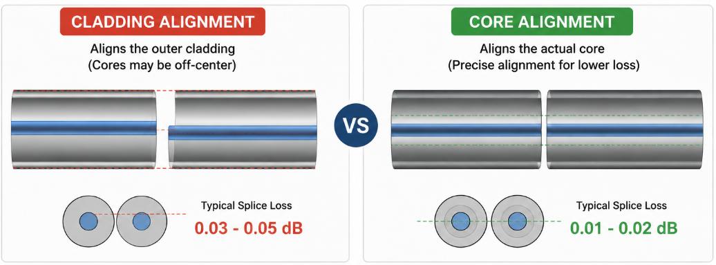 Let’s be honest: In the world of fiber optics, your splicer is your lifeline. Whether you are terminating a single residential drop or splicing a 432-count backbone cable, the quality of your splice dictates the quality of your network. But with prices ranging from $500 to $ 5,000 how do you choose the right one? Buying the most expensive model is overkill for some, while buying a budget “clamshell” splicer could cost you thousands in repeat truck rolls. Here are the five critical criteria you need to evaluate before swiping your credit card. 1. Core Alignment vs. Cladding Alignment Cladding Alignment (Budget): These units align the outer glass layer of the fiber optic cable. They are fast and cheap, but they are also less precise (typical loss: 0.03 dB to 0.05 dB). Best for: FTTH (Fiber to the Home) drop cables, temporary restoration, or CCTV installs. Core Alignment (Professional): These units use a camera and motors to look inside the fiber and align the actual light-carrying core. They are slower to process but dramatically more accurate (typical loss: 0.01 dB to 0.02 dB). Best for: Long-haul networks, OSP (Outside Plant), and any telco-grade work. 2. Single-Fiber Fusion Splicer vs Ribbon Fusion Splicer A single-fiber fusion splicer is designed to splice one optical fiber at a time. It is the most commonly used type of fusion splicer in FTTH deployment, telecom maintenance, enterprise cabling, and field repair work. A ribbon fusion splicer (also called a mass fusion splicer) is designed to splice multiple fibers simultaneously, usually ribbon fibers containing 4, 8, or 12 fibers in a flat ribbon structure. 3. Environmental Durability The lab specs on the box don’t matter if the splicer dies the first time it rains or you drop it off a ladder. Look for the Big Three resistance ratings: Dust & Water (IP…Read more →
-
Fiber splicing is also called fiber optic cable splicing, that is using a special equipment optical fiber fusion splicer to fuse two bare fibers that are not connected into a whole. Fiber splicing is not as simple as fusing two bare fibers together, it’s a process: stripping fiber cable jacket and tubes, securing the fiber, cleaving the fiber, stripping the coating, fusion splicing the fiber, placing splice into splice tray and so on, and is a series of meticulous work. Especially in the end face preparation, fusion splicing, placing splice and other aspects, the operator is required to observe carefully, think over, and standardize the operation. Tool: Fusion splicer, 95% industrial alcohol, fiber optic stripper, fiber cleaver, absorbent cotton or dust-free paper, needle-nose pliers, wire stripper, connectors, light source, optical power meter, cutter, VFL, vice and so on. Environment: Dust-free environment is the best, or where dust is not visible. Advantages of fiber splicing: 1)Small loss (0.01~0.02) 2)Basically not affected by the environment, low maintenance cost Disadvantages of fiber splicing: 1)Expensive splicing cost (fusion splicer is expensive) 2)Fusion splicer is inconvenient to operate due to the limitation of its own battery and environment (strong wind, cold weather, etc.) Following is the steps of fiber splicing, taking Optical Fiber Splice Closure as example (Optical Fiber Terminal Box, ODF Distribution Frame or other equipments are similar) 1.Strip the outer armor protection layer of the optical cable and secure Cut the fiber optic cable (Cutter) at a distance of 0.6 to 0.8 meters from one end, use the cutter to remove fillers (the layer attached to the outer sheath of the optical cable), cut the wire with a vise and leave a few centimeters of wire to secure the cable. Wipe off the grease outside the loose tube. Open the splice closure, loosen the…Read more →
-
What is IOLM? Intelligent Optical Link Mapping (iOLM) is a technology that automates the process of configuring the OTDR to capture and analyze all the information on a fibre regardless of its length and the number of connectors and splice cable on the span. How OTDR work? There are two tiers, or “levels”, available for certifying fibre optic cabling. The first certification is a measurement of the total insertion loss (previously called attenuation) of the cabling from one end of the fibre link to the other, The second certification provides loss information about each component of the link. An OTDR (optical time domain reflectometer) is used to perform the second certification. The primary advantage of the second certification test is that it provides information about each connection, splice and cable segment in the link and offers a graphical representation of the components and their performance. OTDR Function When testing newly installed cabling the report is a snapshot of the system that can be compared to later tests to identify any changes in the cabling. An OTDR is unrivalled for troubleshooting because it shows the operator exactly where faults are located in the cabling, expediting the repair process. Advantage and disadvantage about short pulse width and long push width Pulse Width has the most impact on measurement results, the pulse width is the duration of the laser pulse for each sample during the trace acquisition. A short pulse width provides excellent resolution and can detect events that are near each other at patch panels where there may be just a few feet between connectors. The downside to a short pulse is that it injects a small amount of power into the cabling and cannot measure long distances. In some cases, the OTDR may not be able to detect the end of…Read more →
-
 Fiber optic cables are at the heart of modern communication networks, powering everything from the internet to television services. Whether you’re building a new network or maintaining an existing one, one of the most essential skills is splicing—connecting two fiber optic cables to create a seamless, low-loss link. Poor splicing can result in signal degradation, costly repairs, and unnecessary downtime, but when done correctly, it guarantees the long-term integrity and performance of your network. This comprehensive guide will demystify the process, outlining not just how to splice fiber optic cable, what is splicing of fiber optic cable, but the rigorous standards that define a professional, lasting installation. Part 1: Understanding the Foundation – What is Splicing of Fiber Optic Cable? Before diving into the technical aspects of fiber optic splicing, it’s important to understand exactly what the process entails. Splicing refers to the process of connecting two fiber optic cables together, either permanently or temporarily. The goal is to create a continuous pathway for light signals, allowing data to travel smoothly through the fiber. There are two primary methods for splicing fiber optic cables: Fusion Splicing: This is the most common and effective method, where the fiber ends are melted together using an electric arc to create a permanent, low-loss connection. Mechanical Splicing: This method uses a special splice holder to align the fibers and a gel or adhesive to secure them in place. While not as efficient as fusion splicing, it’s often used in emergency situations or where fusion splicing equipment isn’t available. Part 2: The Hands-On Process – How to Splice Fiber Optic Cable (Fusion Method) Achieving a perfect splice is a ritual of patience and precision. Here is a detailed, step-by-step breakdown. Stage 1: Preparation & Safety Gear Up: Safety glasses are mandatory. Invisible glass shards from cleaving…Read more →
Testimonials

Lomoveishiy – Finland11

