
-
 If you work in data centers, telecom, or fiber optic networking, you have likely heard the acronyms MPO and MTP thrown around. But what exactly is an MPO/MTP connector? More importantly, the MPO/MTP connector is primarily used to address one critical problem: space constraints. As bandwidth demands explode, traditional connectors (like LC or SC) simply cannot keep up. Enter the multi-fiber solution. What is an MPO/MTP Connector? Before we dive into usage, let’s clarify the alphabet soup. MPO (Multi-fiber Push On) is the standard defined by IEC 61754-7. MTP is a registered trademark of US Conec for a specific brand of MPO connector that offers improved mechanical performance. When people search for MPO MTP, they are generally referring to the same physical shape—a rectangular connector that holds 12, 24, or even 48 fibers in a single ferrule. However, understanding the MTP vs MPO connectors debate is crucial for procurement. Standard MPO connectors can have floating ferrule issues and lower cycle life. MTP connectors feature improved guide pins, metal pin clamps, and an elliptical spring design for better optical performance. MPO MTP Connector Is Mainly Used For What? The question many network engineers ask is: MPO MTP connector is mainly used for what applications? The answer lies in environments that require high-speed, high-density fiber connectivity. 1. Data Centers One of the most common uses of MPO MTP connectors is in data centers. Modern data centers contain thousands of servers, switches, and storage systems that require massive amounts of bandwidth. In data centers, running 144 individual fibers across the room is a nightmare. Technicians use trunk cables with MPO/MTP connectors on the ends. A single 24-fiber MPO trunk handles the same traffic as 12 duplex LCs but takes up 1/10th of the rack space. MPO MTP cabling enables administrators to connect large numbers of fibers in…Read more →
-
 If you have recently upgraded to a fiber optic connection, you’ve likely noticed a small device installed by your Internet Service Provider (ISP). That device is the ONU (Optical Network Unit). While most users understand that the ONU converts light signals into internet data, fewer understand a critical feature now built into these devices: IPv6 on ONU. As the world runs out of traditional IPv4 addresses, the shift to IPv6 is no longer optional. But what exactly is IPv6, what is it used for, and how does it actually work inside a fiber network? Let’s break it down. First, What Is IPv6? (And What Is It Used For?) Before we dive into the ONU, let’s clarify the protocol itself. IPv6 (Internet Protocol version 6) is the latest version of the Internet Protocol. Its primary job is to identify and locate devices on a network so they can communicate over the network. You can think of it as a postal address for your smartphone, laptop, or smart TV. So, IPv6 what is it used for? In short, it solves the “address exhaustion” crisis of IPv4. While IPv4 supports about 4.3 billion addresses (which we’ve run out of), IPv6 supports 340 undecillion addresses—enough for every grain of sand on Earth. Practically, it is used for: End-to-end connectivity without needing clunky workarounds like NAT (Network Address Translation). Enhanced security with mandatory IPSec support. More efficient packet processing, which improves speed. How IPv6 Work: The Basics To understand how IPv6 works, you need to forget the dotted-decimal notation of IPv4 (like 192.168.1.1). IPv6 uses hexadecimal digits separated by colons (e.g., 2001:0db8:85a3::8a2e:0370:7334). Here is the simple flow: Address Autoconfiguration (SLAAC): Devices generate their own unique IPv6 address without needing a central DHCP server (though DHCPv6 can still be used). Neighbor Discovery (NDP): Devices on the same…Read more →
-
 If you work with fiber optic networks, an OTDR (Optical Time Domain Reflectometer) is one of the most valuable tools for troubleshooting and certifying fiber links. However, many technicians, especially beginners, overlook one important accessory—the launch cable. People often ask: What is a launch cable used for? Why use launch cable in OTDR testing? Is a launch cable for OTDR really necessary? The answer is that a launch cable is essential for obtaining accurate and reliable test results. If this component is not used, the OTDR may fail to accurately analyze the first connector or splice, as these events occur within the instrument’s dead zone. This can lead to incorrect loss measurements and missed faults. In this guide, we’ll explain how a launch cable works and why it is important for your testing application. What Is a Launch Cable? A launch cable is a specially prepared length of optical fiber that is connected between the OTDR and the fiber link being tested. It is typically stored inside a protective reel or carrying case to prevent damage during transportation and field work. The launch cable is also known by several other names, including: Launch fiber Pulse suppressor cable Dead zone eliminator OTDR launch box Although the cable itself may appear to be just a spool of fiber, it plays a critical role in OTDR measurements. Instead of allowing the OTDR to inject light directly into the network, it provides additional fiber length so that the testing instrument can stabilize before reaching the first connection in the actual fiber link. Without this extra distance, important events at the beginning of the cable may be hidden from the OTDR analysis. What Is a Launch Cable Used For? The primary purpose of a launch cable is to move the first connection point outside of the OTDR’s…Read more →
-
 In modern fiber optic communication systems, the cleanliness of connectors directly affects network stability and transmission quality. A tiny dust particle on the fiber end face can significantly increase insertion loss or even interrupt the optical link entirely. This problem becomes even more critical in high-density cabling systems that use MPO fiber connectors. Unlike traditional single-fiber connectors, MPO connectors contain multiple fibers inside one ferrule. Because several optical channels share the same connection surface, contamination can affect many fibers simultaneously. Improper cleaning methods may also scratch the ferrule, damage guide pins, or permanently reduce optical performance. This guide explains what is an MPO connector, why proper maintenance matters, and how to clean MPO connectors safely without damaging the ferrule surface. Table of Contents What Is an MPO Connector? Why Cleaning MPO Connectors Is Important Common Mistakes That Damage MPO Ferrules Step-by-step cleaning procedures Best Practices for Protecting MPO Connectors What Is an MPO Connector? Before learning the cleaning process, it is important to understand what is an MPO connector and why it requires more careful handling than standard fiber connectors. An MPO (Multi-fiber Push-On) connector is a high-density fiber optic connector designed to combine multiple optical fibers into a single compact interface. Instead of supporting only one fiber like LC or SC connectors, MPO connectors can support multiple fibers simultaneously, allowing much higher port density and faster deployment in large optical networks. Why Cleaning MPO Connectors Is Important Because MPO connectors handle multiple optical signals at the same time, their ferrule alignment must be extremely precise. Even very small contamination particles can block or scatter light across several fiber channels. This is why MPO connectors require specialized cleaning tools and proper maintenance procedures. Many fiber optic problems are caused by dirty connector end faces rather than equipment failure. Dust, oil,…Read more →
-
If you recently installed fiber internet, you may have noticed a cable connected to a small box called an ONT. Many people ask: What is the ONT cable, what does it do, and where should it connect? Understanding the ONT cable is important because it is the main connection that brings fiber internet into your home. In this guide, we will explain the ONT cable meaning, how it functions, and answer the common question: where does the ONT cable go? What is the ONT Cable? Technically, the term “ONT cable” is a bit of a nickname that people use in different ways. It usually refers to the fiber optic cable that plugs into the ONT (Optical Network Terminal), which is the small box that connects your home to the internet provider’s fiber network. However, many people also call the Ethernet cable that exits the ONT the “ONT cable” because that’s the cord they actually touch when setting up their router. Understanding this small difference can save you a lot of confusion when talking to technical support or reading online guides. To understand the cable, you first need to understand the box: ONT (Optical Network Terminal) = A device that converts light signals from the street into internet signals your router understands. Without the ONT, the fiber optic light signals coming into your home would be useless to standard home routers. This box is usually provided by your internet service provider and mounted on a wall in your garage, basement, or utility closet. The “ONT Cable” = Typically, the fiber optic cable entering the ONT, or the Ethernet cable leaving it to connect to your router. Depending on which cable you are talking about, the function and appearance change completely. ONT Cable Meaning Explained When people search for “ont cable meaning,” they…Read more →
-
When you’re building or expanding a fiber optic network, a common question arises: how do you connect an OLT to another OLT? Unlike connecting an OLT to an ONT (standard last-mile connection), linking two Optical Line Terminals is a less common but highly valuable technique called cascading. This method is essential for expanding network coverage, reducing fiber costs, and optimizing core uplink ports. Many new network engineers assume that OLTs can only connect directly to a core router or switch, but in reality, cascading them opens up much more flexible network topologies. Here is a step-by-step technical breakdown of how to achieve a successful OLT-to-OLT connection, including the physical setup, configuration logic, and important vendor considerations. What is OLT Cascading? Cascading means connecting one OLT directly to another using high-speed uplink ports (typically 10G or 40G SFP+ modules) instead of running separate cables from each OLT back to the core network switch. In simpler terms, you are treating one OLT as an extension of the other, rather than as an entirely independent device. This creates a parent-child relationship where the downstream OLT forwards all of its subscriber traffic through the upstream OLT before reaching the internet. Why Connect OLT to OLT? Save Ports: You conserve valuable uplink ports on your core switch or router. If you have ten OLTs and each requires its own uplink port, you might run out of ports quickly. Cascading allows you to connect multiple OLTs using just one or two core uplink ports. Extend Reach: You can push fiber connectivity to remote areas without building out expensive new fiber runs to the data center. Instead of laying a long, costly fiber cable from a remote village all the way back to your central office, you can run a shorter cable to a nearby OLT and cascade…Read more →
-
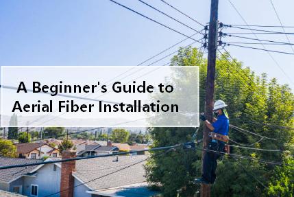 When it comes to expanding fiber optic networks, especially in rural areas or along existing utility corridors, getting the cable from point A to point B quickly and cost-effectively is a major challenge. Trenching is expensive and disruptive. Pole attachments can be complex. That’s where lashed aerial cable comes in. For decades, telephone and cable TV companies have used lashing to secure copper cables. Today, the same proven method is widely used for fiber aerial cable installations. But what exactly is cable lashing, and how do you do it properly? This guide covers everything you need to know about lashed aerial fiber installations. Table of Contents What is Cable Lashing? Why Lash an Aerial Fiber Cable? Installation Steps Advantages Over Other Aerial Methods Conclusion What is Cable Lashing? Cable lashing is the process of securing a cable (in this case, a fiber optic cable) to a supporting messenger wire using a smaller-gauge wire wrapped tightly around both. The messenger wire—typically made of stranded steel—is first strung between poles or structures. Then, the fiber cable is placed alongside it, and a lashing wire (stainless steel or galvanized) is wound around both to hold the fiber firmly in place. Think of it like tying a package with a string, but done automatically over long spans. A lashing machine—either manual or powered—rides along the messenger wire, spinning the lashing wire around the messenger and the fiber cable as it moves. Important distinction: Lashing is not the same as ADSS (All-Dielectric Self-Supporting) cable. ADSS cable is designed to be hung directly between poles without a messenger. Lashing requires a separate messenger strand. Why Lash an Aerial Fiber Cable? Network operators choose lashed aerial construction for several compelling reasons: Lower cost than underground: No trenching, no boring, no road cuts. You simply use existing poles…Read more →
-
 If you work in industrial networking, security, or legacy telecom migration, you’ve likely faced a common headache: You need to keep old analog phones, fax machines, or alarm systems running, but the copper lines are being decommissioned or are too far away. Enter the world of POTS (Plain Old Telephone Service) multiplexers. These devices allow you to extend analog voice signals over modern backhaul networks. But which one is right for your project? Today, we are comparing two heavy hitters: POTS over Fiber Multiplexers vs. POTS over E1 Multiplexers. The Common Goal: Analog over Digital Both devices do the same fundamental job. They take a standard RJ-11/POTS line (2-wire), convert the voice into digital data, send it over a long distance, and convert it back to a dial tone on the other side. They operate differently and are suitable for different network architectures. What Is a POTS Multiplexer? A POTS multiplexer is a communication device that combines multiple analog telephone lines into a single transmission channel for long-distance transport. At the receiving end, the signals are separated and restored to standard analog phone interfaces. The primary purpose of a POTS multiplexer is to simplify cabling complexity while extending the distance of voice communication. Depending on the transmission medium, these multiplexers are generally divided into: POTS over Fiber Multiplexers POTS over E1 Multiplexers POTS over Fiber Multiplexer This device uses optical fiber as its transmission medium. You plug your phone into the “FXS” port on the local unit, plug fiber into the SFP/optical port, and run the cable to a remote unit. The Good: Distance: Fiber goes miles (up to 80km or more) without repeaters. Perfect for campus settings or rural mining sites. Immunity: Zero interference from lightning, EMI/RFI, or ground loops. Fiber is dielectric. Bandwidth: Most units also offer Ethernet ports…Read more →
-
 If you are researching business phone systems or simply trying to cut down your home phone bill, you have likely stumbled upon the great debate: POTS vs VoIP. For over a century, traditional phone lines were the only option for making a call, and they became so reliable that most people never thought about the technology behind them. But now, internet-based calling is taking over the industry, offering features that analog lines could never dream of supporting. So, how do you choose between these two very different systems? To make the right decision, you need to understand every difference between VoIP and POTS—from cost and call quality to reliability and advanced features. By the end of this post, you will have a clear answer to the question of VoIP or POTS for your specific situation. What is POTS? POTS stands for “Plain Old Telephone Service.” These are the copper wires running from telephone poles into your home or office, a technology that has existed for ov er a century. When you plug a phone into the wall jack and hear a dial tone, you are using POTS. This system was originally designed for analog voice transmission and has changed very little since the early 1900s. How it works: It creates a dedicated physical circuit between you and the person you are calling. That entire circuit remains open and reserved for your conversation for the duration of the call, which is why it is often called “circuit-switched” technology. This dedicated path ensures that no other internet traffic or data can interfere with your voice transmission. What is VoIP? VoIP stands for “Voice over Internet Protocol.” Instead of relying on copper wires owned by a telephone company, it uses your existing broadband internet connection to transmit calls. Your voice is converted into…Read more →
-
In the world of telecom, two technologies rarely get mentioned in the same sentence: Ethernet, the flexible and ubiquitous king of local area networking, and SDH (Synchronous Digital Hierarchy), the rigid, time-tested backbone of legacy voice networks. Yet, for over two decades, engineers have been successfully marrying these two worlds using a technique called Ethernet over SDH (EoS). But why would anyone want to run modern Ethernet traffic over what many consider an “old” telecom standard? And how does something like STM 1 SDH fit into a world dominated by gigabit Ethernet? More importantly, how do you actually make the connection in the real world? Let’s break down the benefits, the real-world challenges, the use cases, and finally introduce the unsung hero of telecom integration: the Ethernet over SDH (STM-1) converter. What Is Ethernet Over SDH? Before diving into pros and cons, let’s clarify the concept. Traditional SDH was built for TDM (Time-Division Multiplexing) traffic—voice calls, leased lines, and constant bit-rate services. It’s incredibly reliable but not very efficient for bursty data like web traffic or email. Ethernet over SDH solves this by encapsulating entire Ethernet frames into SDH virtual containers. Think of it as putting a modern shipping container (Ethernet) onto a highly reliable, pre-scheduled train network (SDH). The train doesn’t care what’s inside the container; it just guarantees to deliver it on time, every time. A common entry point for this is STM 1 SDH, which operates at 155.52 Mbps. That might sound slow compared to modern Ethernet, but for many enterprise branches, utilities, or government sites, 155 Mbps of guaranteed, jitter-free bandwidth is far more valuable than a “best-effort” 1 Gbps broadband link. Why Telecoms Still Use EoS(Benefits) Unmatched Reliability (99.999% Uptime) SDH networks were designed for voice. Downtime was not an option. When you run Ethernet…Read more →
-
Fiber optic networks rely heavily on transceiver modules to transmit data efficiently across different distances and network environments. Among the most commonly used standards in Ethernet SFP modules are SX, SR, LX, and LH. While they may look similar at first glance, each type serves a distinct purpose based on transmission distance, wavelength, and fiber type. In this guide, we break down these four optical standards clearly and practically so you can understand when and why to use each one. What Do SX, SR, LX, and LH Mean? These labels define optical transmission standards used in fiber optic transceivers, especially SFP (Small Form-factor Pluggable) modules. They generally indicate: Distance capability Wavelength used Fiber compatibility (multimode or single-mode) Here’s a simple overview: SX (Short Wavelength) SR (Short Reach) LX (Long Wavelength) LH (Long Haul) Now let’s look at each one in detail. SX vs SR vs LX vs LH: Key Differences SX (Short Wavelength)–Short Distance Multimode Connectivity SX modules are designed for short-range transmission over multimode fiber (MMF). Key Characteristics: Wavelength: ~850 nm Fiber type: Multimode fiber (OM1/OM2/OM3/OM4) Typical distance: up to 300–550 meters (depending on fiber quality) Common usage: LAN, data centers, campus networks SX is ideal when devices are physically close and high-speed connectivity is needed over short distances. SR (Short Reach)–IEEE Standard Short-Distance Solution SR is often considered the modern IEEE-standard equivalent of SX, widely used in Ethernet systems, such as 1G, 10G, 25G, and beyond. Key Characteristics: Wavelength: ~850 nm Fiber type: Multimode fiber Typical distance: ~300 meters (OM3), up to ~400–500 meters (OM4) Standard compliance: IEEE 802.3 (e.g., 10GBASE-SR) SR modules are extremely popular in modern networking due to their efficiency and cost-effectiveness for short-range high-speed links. LX (Long Wavelength)–Standard Single-Mode Long Distance LX modules are designed for longer distances using single-mode fiber (SMF). Key Characteristics: Wavelength: ~1310 nm…Read more →
-
 In telecommunications and networking, choosing the right transmission technology can directly affect network performance, reliability, and long-term operating costs. Two technologies that are often compared are Ethernet and SDH. Although both can transport data over fiber optic networks, they were designed for different purposes and follow different operating principles. Understanding ethernet vs sdh is especially important for telecom operators, enterprises, system integrators, and anyone upgrading legacy infrastructure. Ethernet is now common in modern IP networks, while SDH remains present in many traditional carrier environments. This article explains What is ethernet, what is sdh technology, how sdh works, and the main differences between them. What Is Ethernet? Ethernet is one of the most widely used networking technologies in the world. It was originally developed for local area networks (LANs), allowing computers, printers, switches, and servers to communicate with each other in the same network. Over time, Ethernet evolved far beyond office networking. Today, it is also used in metropolitan networks, data centers, industrial systems, surveillance systems, and broadband access networks. Because Ethernet is flexible and cost-effective, it has become the standard for modern digital communication. Key Characteristics of Ethernet Packet-Based Transmission Ethernet sends information in small units called frames or packets. Each packet contains source and destination addresses, control information, and payload data. This packet-based method allows multiple devices to share the same network efficiently. It also makes Ethernet highly suitable for internet traffic, cloud applications, VoIP, and streaming services. Flexible Speed Options Ethernet supports many speed levels, including: 10 Mbps 100 Mbps 1 Gbps 10 Gbps 25 Gbps 40 Gbps 100 Gbps and higher This means businesses can start with lower speeds and upgrade gradually as demand increases. Easy Expansion Ethernet networks are relatively simple to scale. New switches, routers, servers, or endpoints can be added without redesigning the entire…Read more →
-
 Modern communication networks rely on systems that can carry large amounts of voice, video, and data traffic over long distances. Before Ethernet and IP-based transport became dominant, telecom operators around the world depended heavily on SONET and SDH to build reliable fiber optic backbone networks. Even today, many carrier and enterprise systems still use these technologies because of their stability and strong protection features. If you are new to telecom networking, this guide explains what SONET and SDH are in telecommunication, how they work, their differences, and why they still matter. What Is SONET and SDH? SONET stands for Synchronous Optical Network. It is a standardized digital communication protocol developed primarily in North America for transmitting data over optical fiber. SDH stands for Synchronous Digital Hierarchy. If you are asking what does SDH stand for, this is the full form. SDH was developed as the international equivalent of SONET and is widely used in Europe, Asia, Africa, and many other regions. Both systems were designed to solve compatibility problems between different telecom vendors and to create a common standard for high-speed fiber transmission. In simple terms: SONET = Mainly the North American standard SDH = International standard Both are used to transport large volumes of traffic synchronously over fiber optic networks. Feature SONET (US/Japan) SDH (Global) Governing Body ANSI ITU-T Base Signal STS-1 (51.84 Mbps) STM-1 (155.52 Mbps) Common Term OC (Optical Carrier) STM (Synchronous Transport Module) Why Did We Need This? Before SONET and SDH, telecom networks used a system called PDH (Plesiochronous Digital Hierarchy). PDH had a massive flaw: it was asynchronous. Every clock in the network was slightly different. To combine two data streams, you had to literally stop one, break it apart, and restart it. This made it almost impossible to access a single phone call buried…Read more →
-
 In the world of fiber optic communications, “more power” is not always better. In fact, too much light can actually destroy sensitive receiver components or cause bit errors due to signal distortion. While engineers often fight to reduce loss from splices and bends, sometimes you need to introduce loss intentionally to save a network. This balances the signal-to-noise ratio and prevents the optical receiver from becoming overloaded. Enter the variable optical attenuator (VOA)—the unsung hero of power management. Unlike a fixed attenuator that forces a static loss value, a VOA gives you the flexibility to change the loss on demand. If you have ever struggled with a receiver that was “blinded” by too much laser light or needed to simulate different link distances during certification testing, you need this device. What Is Variable Optical Attenuator? Let us start with the basics. If you ask, what is variable optical attenuator, the answer is simple: It is a device that reduces the optical power (light) in a fiber optic cable by a controllable amount. This reduction is measured in decibels (dB), and even small changes of 0.5 dB can significantly impact system performance, especially in long-haul networks. Unlike a fixed attenuator (which drops the signal by a specific value like 5dB or 10dB every time, with no room for adjustment), a VOA allows you to dial in the exact loss you need. Think of it like a dimmer switch for light bulbs versus a standard on/off switch. The dimmer can go from 0% to 100% gradually, whereas the on/off switch only gives you two extremes: full brightness or total darkness. Why Do Fiber Networks Need a Variable Optical Attenuator? Many users wonder why attenuation is necessary when fiber optic systems are designed for low signal loss. The reason is that low loss is…Read more →
-
 If you are diving into the world of fiber optics, specifically GPON or XGS-PON networks, you have likely hit a confusing crossroads. On one side, you have the traditional ONT (Optical Network Terminal) — the big plastic box your ISP usually gives you. On the other, you have the sleek, tiny SFP ONU Stick. But what is the actual difference? And when should you choose one over the other? First, the critical similarities: Both devices perform the same core job — converting optical GPON/XGS-PON signals into electrical Ethernet signals that your router can understand. Both authenticate with your ISP using a serial number and password. Both support similar upstream/downstream speeds (typically 2.5Gbps down / 1.25Gbps up for GPON, or 10Gbps symmetric for XGS-PON). The fundamental technology inside is nearly identical; only the packaging and integration differ. So if they do the same thing, why choose one over the other? Let’s dive in. What is a Traditional ONU/ONT? First, let’s define the incumbent. An ONT (or ONU) is the interface between the fiber optic cable from your ISP and your home network (Ethernet). It acts as a translator, converting light signals from the fiber line into electrical signals that your router can understand. Form Factor: A standalone plastic box (think cable modem size). It usually sits on a desk, shelf, or is mounted to a wall, taking up valuable real estate near your router. Power: Requires a dedicated wall outlet (12V DC). This means you need a free power socket nearby, and you have yet another power brick to manage behind your entertainment center. Connectivity: Usually has 1x SC/APC fiber port in the back, and 1x RJ45 Ethernet (or 4x ports) in the front. You must run a short Ethernet jumper cable from the ONT to your router’s WAN port. Function:…Read more →
Testimonials

Lomoveishiy – Finland11

