
-
 Fiber optic networks rely on countless connection points where cables are spliced, branched, or repaired. These exposed splices must withstand moisture, dust, mechanical stress, and temperature fluctuations—and that is precisely the role of a fiber optic closure. Whether you are deploying FTTH, expanding a metropolitan backbone, or repairing damaged cables, proper fiber optic closure installation directly determines long-term network reliability and future maintenance costs. What Is a Fiber Closure? Step-by-Step Fiber Optic Closure Installation Common Mistakes to Avoid How to Maintain a Fiber Closure What is a fiber closure? It is a protective enclosure that houses fiber splices and cable joints. Its core functions include waterproofing and dustproofing, organizing fiber slack, providing mechanical strain relief, and enabling future expansion or re-entry. Without a properly installed closure, fiber connections become vulnerable to water ingress, cable tension, and physical damage. Why does installation quality matter? A poorly installed closure rarely fails immediately. Problems typically surface months or years later—as increased insertion loss, fiber breakage, water penetration, intermittent outages, higher operational costs, and shortened network lifespan. A single properly installed closure can protect your network for over a decade. The cost of locating and repairing a failed closure—whether buried underground or suspended on a pole—far outweighs the upfront investment in a quality closure and disciplined installation practices. Step-by-Step Fiber Optic Closure Installation A successful fiber optic closure installation is a systematic process. It begins with planning and ends with thorough testing. Choosing the right closure for the job is the first critical step, considering factors like application (aerial, buried, or underground), cable type, and the number of fibers to splice. 1. Preparation is Key Before you even open the closure kit, the work begins. Site Selection: The mounting location must be chosen with care. For aerial installations, a minimum height (e.g., 5 meters above ground)…Read more →
-
 If you are responsible for maintaining a fiber optic network, the OTDR is your most valuable diagnostic asset. However, to use it effectively, you need to understand not just how to press the button, but why it works and what it is telling you. In this guide, we will break down the core function of the OTDR, explain why testing is critical for network health, dive into the physics of how it operates, list the necessary equipment, and provide a meticulous step-by-step guide. Why Is OTDR Testing Important? Equipment Needed for OTDR Testing How to Use OTDR: Step-by-Step Guide What Is the Function of OTDR? How Does an OTDR Work? Why Is OTDR Testing Important? You might wonder, “If my network is working, why do I need to test with an OTDR?” The answer lies in proactive maintenance and rapid troubleshooting. OTDR testing is crucial for three main reasons: Acceptance Testing (New Installations): When a contractor lays new fiber, you need to verify the quality of their splices. An OTDR provides a “pass/fail” report for every splice point, ensuring the installation meets the loss budget specified in your design. Rapid Outage Restoration: When a fiber breaks, a power meter will only tell you that the link is dead. An OTDR will tell you exactly how many meters down the trench the break occurred, allowing your crew to dig in the right spot and reduce downtime from hours to minutes. Preventative Maintenance: Water ingress, stress from ice, or rodent damage can cause “microbends”—tiny deformations that don’t break the fiber but increase loss over time. OTDR testing during routine maintenance catches these issues before they cause a complete network failure. Equipment Needed for OTDR Testing Before learning how to use an OTDR tester, it is important to gather the proper equipment. Using…Read more →
-
 Fiber optic cables are the silent workhorses of the digital age, carrying vast amounts of data across continents and into our homes. But when a connection slows down or fails, how do technicians diagnose the problem without digging up miles of cable? The answer lies in a sophisticated instrument known as an Optical Time Domain Reflectometer (OTDR). If you have ever wondered what the purpose of an OTDR is, think of it as a radar system for fiber optics. Its primary job is to analyze the “health” of a fiber optic cable by locating faults, measuring losses, and evaluating the quality of the link—all from just one end of the cable. This capability makes it an indispensable tool for installation, maintenance, and troubleshooting. In this comprehensive guide, we will explain what it measures, and why every fiber technician relies on it to keep the world connected. What Is the Purpose of OTDR? What Does an OTDR Measure? Conclusion The Primary Purpose of an OTDR Unlike a simple optical power meter, which only measures the total light loss between two ends of a fiber, an OTDR provides a detailed visual “map” of the entire optical link. This allows technicians to perform critical tasks that are impossible with other tools. The main purposes of an OTDR include: Locating Fiber Breaks: When a network goes down, time is money. Instead of manually inspecting kilometers of cable, an OTDR pinpoints the exact location of a break within a few meters. For example, if a 12 km fiber suddenly loses signal, the OTDR can report a break at exactly 8.37 km, allowing technicians to begin repairs immediately. Measuring Overall Fiber Loss: Every fiber introduces attenuation (signal loss). An OTDR verifies that the measured loss aligns with design expectations. Typically, single-mode fibers have an attenuation of…Read more →
-
 In the world of fiber optic certification, the pressure is on to deliver accurate results quickly and cost-effectively. For technicians and network engineers, the question often isn’t if they should perform bi-directional testing, but how to do it most efficiently. This is where loopback testing comes into play—a powerful technique often enhanced by intelligent software like the iOLM OTDR(intelligent Optical Link Mapper). Here’s everything you need to know about loopback OTDR testing: what it is, why you should use it, and how iOLM technology is revolutionizing the process. What Is Loopback Testing in OTDR? Why Perform a Loopback Test? How to Perform a Loopback Test: The Step-by-Step Process The Game-Changer: iOLM Feature Loopback Testing vs Bidirectional Testing When is Loopback Testing the Right Choice? What Is Loopback Testing in OTDR? First, let’s demystify the concept. At its core, loopback OTDR testing is a method that lets you use a single OTDR fiber loopback tester at one site to test two fibers simultaneously. The setup is simple: you place a loopback device (a simple fiber jumper) at the far end, connecting two fibers of a pair. The OTDR at the near end sends light down the first fiber, through the loopback at the far end, and back along the second fiber to the OTDR. This creates a continuous loop. This single-ended measurement technique effectively doubles testing efficiency, cutting the number of physical tests required in half. Why Perform a Loopback Test? There are several compelling reasons to choose fiber loopback tester for your fiber certification projects: Equipment Cost Savings The most obvious advantage is that you need only one instrument rather than two. Buying or renting one OTDR is cheaper than two, which is particularly beneficial when certifying a smaller number of fibers. Testing Efficiency Testing two fibers at once cuts the…Read more →
-
 In the world of high-speed fiber optics, a detail smaller than a grain of sand can determine whether your network runs flawlessly or suffers from mysterious signal degradation. If you’ve ever shopped for fiber patch cables or optical modules, you’ve likely encountered three cryptic abbreviations: PC, UPC, and APC. These aren’t connector types like LC or SC—they refer to the polishing style of the connector ferrule (the ceramic tip that holds the fiber). Choosing the wrong type of polish can increase signal loss, degrade network performance, or even cause permanent damage to expensive equipment. This guide will explain the differences between PC, UPC, and APC connectors, help you select the right one for your application, and highlight critical warnings you can’t afford to ignore. What Are PC vs UPC vs APC Fiber Connectors? Key Differences at a Glance Performance Deep Dive When to Use Each Type How to Select the Right Connector Best Practices 1. What Are PC vs UPC vs APC Fiber Connectors? PC, UPC, and APC describe how the end face of a fiber connector is polished. This finish determines how much light is reflected toward the source—a value known as return loss (or back reflection). The higher the return loss (expressed as a negative dB value, e.g., -60dB is better than -40dB), the less reflection and the better the connector performs. PC (Physical Contact) PC connectors feature a slightly curved or spherical end face. This design ensures the two fiber cores make physical contact when mated, eliminating the air gap that caused problems with older flat-polished connectors. PC was the industry standard in the 1980s but has largely been replaced by its improved successor, UPC. Its return loss is typically around -40dB. UPC (Ultra Physical Contact) UPC is an evolution of PC. It uses the same spherical convex shape but with…Read more →
-
 For years, Power over Ethernet (PoE) has been one of the most practical solutions for powering IP cameras, wireless access points, VoIP phones, and other network devices through a single Ethernet cable. However, as networks move toward higher bandwidth, longer transmission distances, greater electromagnetic interference immunity, and improved electrical safety, Power over Fiber (PoF) is attracting growing attention. In particular, power over fiber PoF technology provides a fundamentally different approach: instead of sending electrical current through copper conductors, it transmits energy as light through optical fiber and converts it back into electrical power at the remote end. So, when comparing PoE vs PoF, which technology is better? The answer depends on the application. PoE remains highly practical for conventional Ethernet deployments, while PoF offers significant advantages in environments where long-distance transmission, electrical isolation, and EMI immunity are critical. This article explains how PoE and PoF work, compares their key differences, examines their applications, and looks at why Power over Fiber may become increasingly important in future network architectures. What Is PoE? What Is Power over Fiber (PoF)? PoE vs PoF: Head-to-Head Comparison Application Scenarios: Where Each Technology Wins Future Outlook Conclusion 1. What Is PoE? Definition and History Power over Ethernet (PoE) is a standardized technology that delivers electrical power alongside data over standard Ethernet copper cabling. The journey began with the IEEE 802.3af standard in 2003, which provided up to 15.4 watts of power per port. This was sufficient for basic IP cameras and VoIP phones. As device power requirements grew, the IEEE 802.3at standard (PoE+) increased capacity to 30 watts, enabling pan-tilt-zoom cameras and high-performance access points. Today, IEEE 802.3bt (PoE++) delivers up to 90 watts per port through all four twisted pairs in a Cat6 cable, making it possible to power LED lighting systems, digital signage, and even…Read more →
-
If you’ve ever stared at an OTDR trace and felt like you were reading a foreign language, you’re not alone. The Optical Time Domain Reflectometer is one of the most powerful—and complex—tools in fiber optic testing. But once you understand the basics, reading OTDR results becomes a straightforward skill that can save you hours of troubleshooting. Here’s how to interpret OTDR results like a pro. Before You Read: Set Up Correctly A clean trace starts with proper setup. Before you even look at the results, ensure you’ve selected the right pulse width (shorter for fine detail, longer for long distances), range (set to at least 1.5x the fiber length), and averaging time (longer reduces noise). Also, always use launch and receive fibers—without them, you can’t measure the loss of the first and last connectors accurately. If your setup is wrong, the trace will mislead you. Table of contents Understand What You’re Looking At The Three Main Event Types You’ll Encounter The Gainer Phenomenon: When Loss Looks Like Gain Three Common Mistakes to Avoid Table: What’s That Event? Understand What You’re Looking At Think of an OTDR trace like a road map of your fiber. The horizontal axis represents distance from the OTDR (0 km is where your tester is connected). The vertical axis shows signal loss in decibels, typically displayed on a logarithmic scale. A healthy fiber shows a smooth, gently sloping line from left to right. This downward slope represents normal signal attenuation as light travels through the fiber. If you see steps, spikes, or sudden drops, that’s where problems live. Keep in mind that the vertical scale can exaggerate small losses—always check the dB/division setting before jumping to conclusions. The Three Main Event Types You’ll Encounter Every OTDR trace will show events along the fiber. Here’s how to identify them: 1….Read more →
-
 For decades, deploying a fiber-to-the-home (FTTH) network meant investing in expensive, bulky chassis-based Optical Line Terminals (OLTs) that consumed significant rack space and power. But what if you could shrink that entire functionality into a device the size of a USB stick? Enter the OLT Stick SFP—a revolutionary pluggable transceiver that packs the intelligence of a full GPON OLT into a compact Small Form-factor Pluggable (SFP) module. Its core value proposition is simple yet transformative: when inserted into a standard Ethernet switch port, it instantly transforms that switch into a fully functional GPON OLT, eliminating the need for dedicated, expensive OLT hardware. Table of Contents What Exactly is an OLT Stick SFP? How Does a Mini OLT GPON Stick Work? Advantages Over Traditional Chassis-Based OLTs Disadvantages and Limitations What Exactly is an OLT Stick SFP? The mini GPON OLT SFP stick adheres to the ubiquitous SFP physical standard—the same form factor used for standard copper or fiber Gigabit Ethernet transceivers. Measuring roughly 70mm x 14mm x 9mm, it’s comparable in size to a typical thumb drive. This compactness allows it to fit seamlessly into any standard SFP port found on enterprise switches, routers, and firewalls. Internal Architecture: More Than Just a Media Converter This is where the OLT Stick truly differentiates itself from standard SFP modules. Standard SFP transceivers are essentially “dumb” media converters. They merely convert electrical signals to optical signals and vice versa, providing a physical layer connection. They have no processing intelligence. The OLT Stick, however, is a “smart” device. It contains an integrated PON MAC (Media Access Control) chip that handles the complex GPON protocol stack. Additionally, it includes a BOSA (Bi-Directional Optical Sub-Assembly) for single-fiber transmission. This built-in intelligence means the stick performs Layer 2 and Layer 3 processing, managing bandwidth allocation, encryption, and ONU registration—tasks…Read more →
-
 If you have ever stared at the empty port on your brand-new switch and thought, “Which SFP do I need?” — take a deep breath. You are not alone. The problem is that SFP modules look like identical silver or metal bricks. But inside, they are wildly different. Using the wrong one can turn a 10-minute installation into a three-hour troubleshooting nightmare. In this guide, I will answer three core questions in extreme detail: Are all SFP modules the same? (Spoiler: No) How do I pick the exact SFP for my network? (A step-by-step framework) How many types of SFP are there? (The full spectrum) How do I pick the exact SFP for my network? Part 1: Are All SFP Modules the Same? Absolutely not. In fact, they are intentionally different. All SFP modules share the same physical dimensions (the “SFF-8431” standard). They all fit into an SFP cage. However, the similarities end there. Here is what changes between modules: Data rate 100Mbps, 1Gbps, 2.5Gbps, 4Gbps, 10Gbps (SFP+), 25Gbps (SFP28) Wavelength 850nm (short), 1310nm (long), 1550nm (extended), or CWDM colors Cable type Copper (RJ45), Multimode fiber (OM1/OM2/OM3/OM4), single-mode fiber (OS1/OS2) Transmit power -3 dBm (short) to +5 dBm (long) — high power can burn short-range receivers Receive sensitivity -17 dBm (poor) to -32 dBm (highly sensitive) DOM support Digital Optical Monitoring (yes/no) — critical for troubleshooting For example, one module may be designed for multimode fiber over a distance of 300 meters, while another is intended for single-mode fiber over 20 kilometers. Installing the wrong module can prevent a network link from coming up or significantly reduce performance. Part 2: How to Choose the Right SFP Instead of memorizing every SFP type first, let’s start with how to choose. This is the practical framework you will actually use. Step 1: What…Read more →
-
How many Types of fiber patch cordsFiber optic networks form the foundation of modern telecommunications, data centers, FTTH deployments, and enterprise networks. Whether you are building a GPON network, connecting switches in a data center, or installing fiber links between buildings, fiber patch cords play a critical role in ensuring reliable signal transmission. Many beginners ask: How many types of fiber patch cord are there? The answer depends on how you classify them. Fiber optic patch cords can be categorized based on fiber mode, connector type, polish type, fiber count, and application environment. In this guide, we will explain the most common fiber optic patch cord types and help you choose the right one for your network. What Is a Fiber Patch Cord? A fiber patch cord, also called a fiber jumper or fiber optic patch cable, is a length of optical fiber terminated with connectors at both ends. It is used to connect optical devices such as switches, routers, ODFs, patch panels, media converters, ONUs, OLTs, and transceivers. Unlike permanent fiber cabling, patch cords provide flexible and removable connections, making installation, maintenance, and upgrades much easier. How many Types of fiber patch cords Are There? There is no single number because fiber patch cords can be classified in several different ways. The most common categories include: Single Mode and Multimode Connector Types Polishing Types Simplex and Duplex Specialized Types of Patch Cords Let’s examine each category in detail. Categorization by Fiber Mode This is the most fundamental classification you will encounter, as it dictates the cable’s core size, light transmission characteristics, and primary application environment. Single Mode Fiber Patch Cord These cables feature an extremely small glass core, typically 9 micrometers in diameter, with a 125-micrometer cladding (9/125 µm). This tiny core allows only a single light ray, or…Read more →
-
 If you’re planning a fiber optic network, upgrading an existing infrastructure, or purchasing networking equipment for the first time, one of the most common questions you’ll encounter is “How many SFP modules do I need?” Although the answer may appear straightforward, many buyers mistakenly purchase the wrong quantity or the wrong type of module, resulting in additional costs and deployment delays. An SFP module is a small but essential component that enables switches, routers, media converters, and other networking devices to communicate over fiber optic cables. Since every fiber connection depends on compatible transceivers at both ends, understanding how to calculate the required number of SFP modules is critical for successful network planning. Whether you’re building a small office network with only a few fiber links or designing a large enterprise or data center infrastructure with hundreds of connections, this guide will explain How many SFP modules do I need, what is SFP module and the calculation process step by step. You’ll also learn common purchasing mistakes and practical examples that make planning much easier. What Is SFP Module? An SFP (Small Form-factor Pluggable) module is a hot-swappable optical transceiver designed to transmit and receive data between networking devices. Instead of permanently integrating optical interfaces into equipment, manufacturers provide SFP ports that allow users to install the appropriate module based on their application. Think of an SFP module as the “translator” between electrical signals generated by your switch or router and the optical signals that travel through fiber optic cables. Without this conversion, the devices would not be able to communicate over fiber. One of the biggest advantages of SFP technology is flexibility. The same switch can support different transmission distances simply by changing the installed module. For example: A short-distance multimode module may support 300 meters. A single-mode module may…Read more →
-
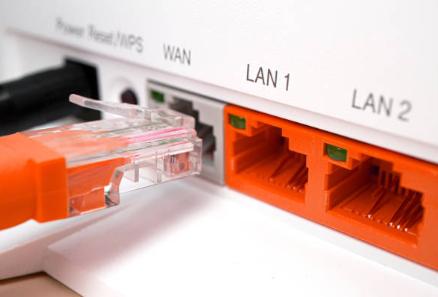 You’ve just signed up for fiber optic internet. The technician installed a small white or black box on your wall, handed you a router, and left. Now you’re staring at a blinking red light, and your phone says “Connected, no internet.” Don’t panic. You are likely dealing with the ONT (Optical Network Terminal). This is the unsung hero of fiber internet—the box that converts light signals into digital data. But here’s the first thing you need to know: not all ONTs are the same. Some are pure ONTs (no Wi-Fi). Others are combo devices with built-in routers and Wi-Fi. Connecting a second router to the wrong type will cause more problems than it solves. This complete guide covers both scenarios. Determining if your ONT needs a Router Device What It Does What It Looks Like Pure ONT (No routing, no Wi-Fi) Converts fiber to Ethernet. No routing, no Wi-Fi. Small white/gray box. No antennas. No Wi-Fi sticker. Single LAN port. Pure ONT with Routing (Routing, No Wi-Fi) Converts fiber AND routes traffic. Assigns IP addresses via DHCP. No Wi-Fi. Same as pure ONT, but your computer gets an IP address when connected directly. ONT/Router Combo (Routing + Wi-Fi) Converts fiber, routes traffic, AND broadcasts Wi-Fi. Has antennas, WPS button, and a sticker with Wi-Fi name and password. Separate Router Distributes internet via Wi-Fi and wired ports. Plastic box with antennas. Multiple blinking lights. Here’s the confusion most people run into: If your ONT is a combo device (already has Wi-Fi) and you plug in a second router without changing settings → Double NAT, slow speeds, gaming issues. If your ONT is a pure device with routing (no Wi-Fi but assigns IP addresses) and you add a router → Double NAT again. You may not need a router at all. If your ONT…Read more →
-
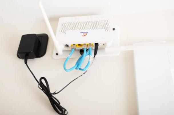 If you have fiber internet service, you may have heard the term ONT but may not know exactly what it is or where it is installed. Many homeowners ask questions such as “where is the ONT located?”, “where is the ONT?”, or “where is ONT box located?” when setting up a new router, troubleshooting an internet outage, or upgrading their home network. The ONT is a critical component of any fiber-optic internet connection. Although it is usually installed by your internet service provider, many users rarely notice it until they need to check connection lights or diagnose a service issue. Because the ONT is often placed in garages, utility rooms, basements, or outdoor enclosures, it can sometimes be difficult to locate. Before looking for the ONT in your home, it helps to understand what the device does and why its installation location is important. Once you know its purpose, identifying and locating the ONT becomes much easier. Why ONT Location Matters Many homeowners assume the ONT can be installed anywhere, but its location can affect network maintenance. Likewise, when internet problems occur, knowing the ONT’s location allows you to quickly inspect status lights and perform basic troubleshooting. Power cycling if you need Unplugging the ONT (not just the router) fixes many fiber connection issues. Your router might show that it’s working perfectly, but if the ONT has frozen up, you’ll have no internet at all. A full power cycle means unplugging the ONT’s power cord, waiting at least 30 seconds (this allows all internal capacitors to drain completely), and then plugging it back in. Battery replacement Some ONTs have a backup battery for VoIP phone service. If you have a home phone line through your fiber provider, your ONT likely contains a small rechargeable battery (similar to a motorcycle battery)….Read more →
-
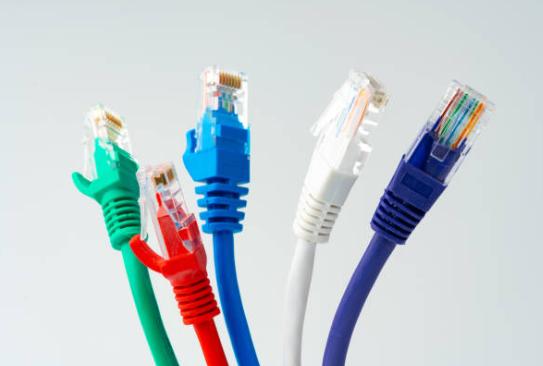 If you’ve ever found yourself staring at a wall of networking cables at the store, confused by labels like Cat 5e, Cat 6, Cat 7, or Cat 8, you’re not alone. The internet is full of conflicting advice, and choosing the wrong cable can bottleneck your speed, increase lag, or force you to rewire your entire home sooner than expected. So, the real question is: Which Cat cable to use for your specific setup? And more importantly, why does it matter Let’s break down everything you need to know to answer which cat cable is the right investment for your home or office—with clear explanations, no marketing fluff. What Does “Cat” Actually Mean? (And Why You Should Care) “Cat” stands for Category. These numbers (5e, 6, 7, 8) aren’t just random model numbers—they represent specific international standards (defined by TIA/EIA) that govern: Bandwidth (measured in MHz): How much data the cable can carry at once. Speed (measured in Gbps): How fast data travels. Distance (measured in feet/meters): How far the signal can go before degrading. Shielding & interference protection (important if you have many cables bundled together). A higher category doesn’t always mean “better for you.” It means “designed for a different job.” Common Ethernet Cable Categories Let’s go through each cable type in detail so you understand exactly what they offer—and what they don’t. Cat 5 (Dead and Buried) Speed: Up to 100 Mbps Bandwidth: 100 MHz Max distance: 328 ft (100m) Explanation: This cable was standard in the 1990s. Today, most home internet plans start at 300 Mbps. Let’s go through each type in detail so you know exactly what they offer—and what they don’t. Do not use it. Cat 5e (The Budget Option) Speed: Up to 1 Gbps (1000 Mbps) Bandwidth: 100 MHz Max distance: 328 ft…Read more →
-
 If you have ever unboxed a new enterprise switch or router, you have likely stared at the back panel and asked yourself a fundamental question: What is the console port on a switch, and why is there another Ethernet port labeled “MGMT”? You are not alone. The debate over console port vs management port confuses even seasoned technicians. Both are used to manage a device, but they serve completely different purposes. One is for emergency surgery; the other is for daily driving. Let’s settle the console vs management port confusion once and for all. What Is a Console Port? A console port is a dedicated interface that provides direct access to the operating system of a network device through a command-line interface (CLI). Unlike normal Ethernet ports, it does not transmit regular network traffic. Instead, it creates a direct communication channel between the administrator’s computer and the device. The console port is primarily designed for out-of-band management, meaning it works independently of the network itself. Even if the switch has no IP address or the entire network is offline, the console connection still functions. This makes the console port extremely valuable during initial installation and emergency troubleshooting. For example, when a brand-new switch is removed from its packaging, it typically has factory default settings and no configured management IP address. Since remote protocols such as SSH cannot be used yet, the console port becomes the only way to access the device. What Is the Console Port on a Switch? The console port on a switch is a physical connector specifically designed for local management. Depending on the manufacturer and model, it may appear as: RJ45 Console Port USB Console Port Mini USB Console Port USB-C Console Port To use it, an administrator typically connects a laptop using a console cable and…Read more →
Testimonials

Lomoveishiy – Finland11

