
-
Changing your GPON ONT WiFi password is one of the simplest yet most important steps to secure your fiber network. Whether you’re setting up a new connection or improving network security, understanding How to Change WiFi Password GPON ONT ensures your connection stays private, stable, and protected from unauthorized access. Whether you have a Huawei, Nokia, ZTE, FiberHome, Baudcom or any other brand of GPON ONT, this guide will walk you through every step in plain, simple language without assuming any prior networking knowledge. Most GPON ONT devices share a surprisingly similar interface layout because they are often built on common reference designs provided by chip manufacturers. That means even if your specific brand isn’t listed in this article, you should still be able to follow along without any trouble. Simply look for menu names that sound similar to the ones described below, and you will likely find what you need. What Is a GPON ONT? A GPON ONT (Optical Network Terminal) is the endpoint device in a fiber-to-the-home (FTTH) network. It converts optical signals transmitted through fiber cables into electrical signals that your home devices can use for internet access. Most modern ONTs are not just simple converters—they integrate multiple networking functions, including: WiFi router capability, allowing wireless connections for smartphones, laptops, and smart devices Ethernet LAN ports, enabling stable wired connections for PCs, IPTV boxes, or switches VoIP ports (in some models) for telephone services Web-based management interface, where you configure settings like SSID, gpon wifi password, and security options Why Change Your GPON WiFi Password? Changing your WiFi password is not just a routine task—it directly impacts your network’s security and performance. However, before we go further, it is important to clarify exactly what this article covers. This guide focuses on changing your WiFi password (also called…Read more →
-
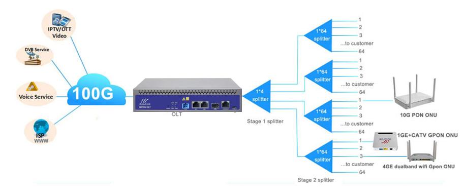 Configuring an OLT GPON system is not just about enabling ports—it involves carefully designing how bandwidth, authentication, and services are delivered across the fiber network. A properly configured OLT ensures stable connectivity, minimizes packet loss, and supports long-term scalability for FTTH and enterprise deployments. In this guide, we expand each step to clearly explain how to configure GPON OLT, with detailed insights and practical recommendations for real deployments. Why We Need to Configure GPON OLT? A GPON OLT (Optical Line Terminal) is the central control point of a fiber access network, but it does not function properly “out of the box.” Without configuration, it is essentially just hardware with optical interfaces but no defined service logic. Configuration is necessary because the OLT must coordinate multiple critical functions simultaneously, including user authentication, traffic forwarding, bandwidth distribution, and service isolation. Proper configuration ensures: Controlled service delivery: The OLT needs rules to determine which user receives which service (Internet, IPTV, VoIP). Without configuration, all traffic would be unstructured and unusable. Efficient bandwidth utilization: GPON networks are shared. Configuration defines how upstream and downstream bandwidth is allocated fairly among multiple ONUs using DBA mechanisms. Secure network access: Authentication rules (SN/LOID binding) ensure only authorized ONUs can join the network, preventing unauthorized access or service theft. Traffic separation and stability: VLAN configuration isolates different services and customers, preventing broadcast storms and reducing interference between services. Scalability for future expansion: A well-designed configuration allows operators to easily add new users, services, or even entire network segments without redesigning the system. Without proper GPON OLT configuration, even high-end equipment will suffer from instability, inefficient traffic handling, and frequent service failures, especially in large-scale FTTH deployments. GPON OLT Configuration Step by Step 1. First Access: Management IP Before you can type a single command or click a button in…Read more →
-
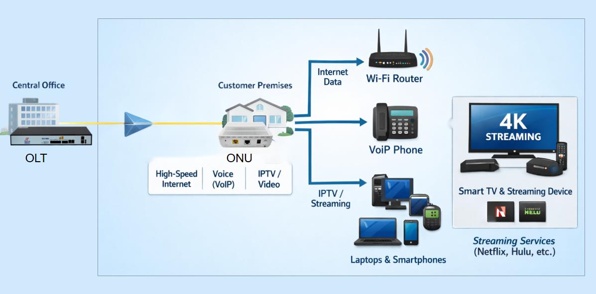 As demand for high-speed internet, IPTV, and cloud services continues to grow, service providers are increasingly turning to PON optical network technology. But for many users and even network planners, one question remains: how does PON work in real-world deployments? In this guide, we’ll go deeper into the fundamentals, architecture, and operation of PON systems, expanding each point to give you a clearer and more practical understanding of the passive optical network definition and how it functions in real deployments. Table of contents What Is a Passive Optical Network (PON)? PON Optical Network Architecture How Does PON Work? Step-by-Step Why Choose a PON Optical Network? What Is a Passive Optical Network (PON)? First, let’s start with the basics. A passive optical network definition is a fiber-optic telecommunications technology that delivers data from a single source to multiple end-users using unpowered (passive) splitters. In simpler terms, it is a way to share a single fiber optic cable among many users without putting electronic switches on the street. The keyword here is passive. Unlike traditional copper networks that require electrical power to run switches and routers in the field, a PON uses passive components like optical splitters. These splitters are made of glass and simply direct light; they do not require electricity, software updates, or cooling fans. These splitters distribute the signal without needing electricity, which dramatically reduces costs and points of failure. Because there are no active electronics in the field, service providers can offer lower prices and experience fewer weather-related outages. PON Optical Network Architecture So, how does PON work in practice? To understand this, you need to look at the three main components of a PON optical network. Without these three pieces working together, data cannot travel from the internet provider to your laptop or smartphone. OLT (Optical Line…Read more →
-
When upgrading to 10G networking, one of the most practical decisions isn’t just whether to deploy 10G—but how. Network engineers typically choose between three common interconnect options, all of which use the SFP+ form factor: 10GBase-T SFP+ (Copper SFP modules)–Uses standard RJ45 Ethernet cabling SFP+ DAC cables(Direct Attach Copper cables)–Pre-terminated twinax cable with integrated SFP+ connectors Fiber SFP+ (Optical modules)–Uses fiber optic cabling with LC or other optical connectors Each has its own trade-offs in cost, flexibility, power consumption, and deployment scenario. This guide explains when it makes sense to choose copper SFP modules over DAC or fiber SFP+, with deeper technical reasoning and real deployment logic. By the end of this post, you will have a clear decision framework for your next 10G deployment—and you will understand why copper SFP modules are often the overlooked sweet spot in short-to-medium range connections. Table of Contents What Is a Copper SFP? The 3 Ways Simple Comparison When to Choose 10GBase-T SFP+ Situations Where You Should NOT Use Copper SFP Practical Deployment Examples What Is a Copper SFP? A copper SFP module (formally called a 10GBase-T SFP+ module) is a transceiver that enables SFP+ ports to transmit data over standard RJ45 Ethernet cables. Instead of converting signals into light (like fiber SFP+ modules), it uses electrical signaling defined by the 10GBase-T standard. Inside each copper SFP module, there is a sophisticated DSP (digital signal processor) that equalizes the signal over long copper runs. This is what allows 10G speeds to travel up to 80–100 meters over ordinary Cat6a or Cat7 cabling. The DSP is also why copper SFP modules consume more power than their DAC or fiber counterparts—but that trade-off is often worth it for the flexibility they provide. In practical terms, a copper SFP module allows network engineers to integrate traditional Ethernet cabling…Read more →
-
If you are new to fiber optics, the number of connection methods can be overwhelming. You have fusion splicing, mechanical splicing, and a growing list of “no-tool” options. Two terms that often cause confusion are the Fiber Fast Connector and the Mechanical Splice. At first glance, they look similar. Both are small, both are used in the field, and both avoid the high cost of a fusion splicer. But are they the same? Absolutely not. Using the wrong one can mean the difference between a stable network and a service call tomorrow. In fact, confusing these two devices is one of the most common mistakes made by new fiber technicians. Let’s break down the confusion, starting with the basics. Table of contents What Is a Mechanical Splice? What Is a Fiber Fast Connector (Fiber Quick Connect)? The Key Differences When Should You Choose Each? Common Mistakes to Avoid What Is a Mechanical Splice? First, we need a clear definition. What is a mechanical splice? It is a permanent (but removable) joining device for two bare optical fibers. Unlike fusion splicing, which melts glass together, a mechanical splice simply holds the two fibers in precise alignment using physical force. Inside a mechanical splice, the two prepared fiber ends are aligned precisely using a V-groove or similar mechanism and then held together with a refractive index matching gel. This gel serves two purposes: it reduces back reflection (return loss) and prevents air gaps that would cause signal loss. The splice is held closed by a latch or a crimp mechanism, which applies constant pressure to keep the fibers touching. Think of it as a “butt connector” for fiber. It takes two separate cables and permanently joins them end-to-end. It does not have a connector body (like an SC or LC plug); it…Read more →
-
When designing or expanding a fiber optic network, one of the most common questions network engineers and procurement managers face is whether OLT and ONU from different brands can work together. Do you have to buy everything from a single vendor, or can you mix a Huawei OLT with a Baudcom ONU? The short answer is yes—but successful interoperability depends on standards compliance, firmware alignment, and proper OLT and ONU configuration. This guide walks you through the technical fundamentals, real-world compatibility scenarios, and practical steps to ensure your multi-vendor GPON network performs reliably. What Is OLT and ONU? (Quick Overview) In a Passive Optical Network (PON): OLT (Optical Line Terminal) is located at the service provider’s central office and manages the network. ONU (Optical Network Unit) is installed at the user side to receive and transmit optical signals. Together, they form the core of fiber access networks such as GPON and EPON systems. What Makes OLT and ONU Compatible? These devices communicate over a passive optical splitter network using industry standards. Most modern networks are built on GPON (Gigabit Passive Optical Network) technology, standardized under ITU-T G.984. This standard defines the physical layer, transmission protocols, and management interfaces—meaning that any GPON-compliant OLT and ONU should, in theory, interoperate. The key mechanism that enables cross-brand compatibility is OMCI (ONU Management and Control Interface) . OMCI allows the OLT to manage the ONU remotely, including configuring services, monitoring performance, and pushing firmware updates. When both devices adhere to the OMCI standard, the OLT can recognize and manage an ONU regardless of its manufacturer. Can You Mix Different Brands of OLT and ONU? Major Brand OLT + Third-Party ONU The most common multi-vendor scenario involves using a dominant OLT platform—such as Huawei or ZTE—with third-party ONUs. This approach is frequently adopted to reduce…Read more →
-
As fiber optic networks scale across data centers, FTTH deployments, and telecom backbones, managing thousands of fiber connections becomes a real challenge. This is where the ODF optical distribution frame plays a critical role. In this guide, we’ll clearly explain the optical distribution frame definition, its structure, functions, and why it is essential in modern fiber networks. Table of contents Optical Distribution Frame Definition Key Functions of an ODF Key Components of an Optical Distribution Frame Types of ODF Optical Distribution Frames Why is an ODF Essential? Optical Distribution Frame Definition Let’s start with a simple and precise explanation. Optical Distribution Frame (ODF) is a fiber management system used to terminate, organize, and distribute optical fibers within a network. An ODF is a frame or shelf designed to house and manage the termination, splicing, and patching of fiber optic cables. It allows for flexible connections between incoming fiber cables (often from the street or between buildings) and outgoing patch cords that connect to active networking equipment like switches or routers. In other words, if you are asking “what is optical distribution frame?”, the answer is: It is the central point where fiber cables are spliced, patched, stored, and protected. An ODF ensures that fiber connections remain: Organized Accessible Scalable Protected from physical damage Key Functions of an ODF 1. Fiber Termination Fiber termination is the process of connecting incoming optical fibers to connectors or adapters, creating standardized interfaces. This allows fibers to be easily connected to transmission equipment such as OLTs, switches, or media converters. A well-designed ODF ensures: Stable and low-loss termination points Compatibility with various connector types (SC, LC, FC) Reduced insertion loss through precision alignment Without proper termination, signal degradation and unstable links are highly likely. 2. Fiber Splicing Splicing is required when extending fiber length or…Read more →
-
 When setting up a structured cabling system for a network, one of the most common points of confusion is the difference between an Optical distribution frame vs patch panel. At first glance, they look similar: they are both flat panels with ports designed to organize cables. However, choosing the wrong one for your environment can lead to wasted rack space, poor cable management, and difficulty scaling your network. To understand which one you need, we first have to look at the scale of the operation and the specific role of each device. What Is an Optical Distribution Frame (ODF)? To understand the optical frame meaning, we have to look at the world of telecommunications, Internet Service Providers (ISPs), and large data centers. An Optical Distribution Frame (ODF) is essentially a patch panel on steroids. While a patch panel is usually a simple box that fits in a standard server rack, an ODF is often a standalone cabinet or a larger chassis system designed for high-density fiber management. The optical frame meaning encompasses several key functions that go beyond simple patching: High Density: ODFs can terminate hundreds or thousands of fiber strands in a single frame. Splicing Integration: Unlike a basic patch panel, ODFs usually contain integrated splice trays. This allows field technicians to splice outside plant cables (coming from the street or other buildings) directly to pigtails that connect to the front adapter ports. Cable Management: ODFs offer superior slack storage. They have dedicated pathways for routing cables without bending them beyond their minimum radius, which is critical for maintaining signal integrity in single-mode fiber. What Is a Patch Panel? If you are managing a local area network (LAN) in an office building, a server room, or a small data closet, you are likely familiar with patch panels. But to answer…Read more →
-
In the modern world, your network is the backbone of your operations. But what happens when you need to connect devices that speak different physical languages—like the legacy copper switch in your office and the high-speed fiber backbone running between buildings? Or when you need to extend a network segment far beyond the 100-meter limit of standard Ethernet cables? The answer lies in a humble but powerful device: the Fiber Media Converter. This comprehensive guide will explain everything you need to know about these essential tools, from their core function to the specific types available and how to choose the right one for your project. Table of contents What Is a Fiber Media Converter? Why Do We Need Fiber Media Converters? Types of Fiber Media Converters How to Choose the Right Fiber Media Converter How to Install and Use a Fiber Media Converter The Future: Will Media Converters Be Replaced by PON? Conclusion What Is a Fiber Media Converter? At its most basic level, a media converter is a networking device that connects two different types of network media, such as converting electrical signals from copper twisted-pair cables (like Cat6) into light signals for fiber optic cables, and vice versa. As our detailed guide on what is a media converter explains, it acts as a seamless translator, making the conversion process invisible to other network devices like switches and routers. This allows different segments of your network to communicate effortlessly. For a network engineer, this functionality is a superpower. For a deeper technical dive, our comprehensive guide for engineers on what does a media converter do breaks down its role in protocol conversion, signal extension, and network design flexibility. In short, a media converter lets you leverage the best of both worlds: the cost-effectiveness and ubiquity of copper for local connections, and…Read more →
-
 Fiber patch cords are essential components in modern optical communication systems, acting as the final connection between critical network devices. Whether you are working in a data center, enterprise LAN, or FTTH deployment, proper installation directly impacts signal quality, network stability, and long-term reliability. Even though fiber patch cords are simple in structure, incorrect handling during installation can lead to significant performance degradation. This guide provides a comprehensive, step-by-step explanation to help you install fiber patch cords correctly and avoid common mistakes. What Is a Fiber Patch Cord? A fiber patch cord, also known as a fiber jumper, is a short optical cable terminated with connectors on both ends. It is used to connect optical equipment such as switches, patch panels, OLTs, and ONTs. These cables serve as the critical link in the optical signal path, meaning their quality and installation directly affect overall network performance. There are two main types: Single mode fiber patch cord – Designed for long-distance transmission with minimal signal loss, typically used in telecom and FTTH networks. Multimode fiber patch cable – Suitable for short-distance communication, commonly used in data centers and LAN environments due to lower cost. Choosing the correct type is essential, as mismatched fiber types can result in severe signal loss or complete communication failure. Why Proper Installation Matters Proper installation is not just a best practice—it is a requirement for maintaining network integrity. When fiber patch cords are installed correctly, they ensure: Consistent low insertion loss, which keeps signal strength stable across connections Minimal return loss, preventing signal reflections that can interfere with transmission Reliable high-speed data transfer, especially in high-bandwidth applications Longer service life, reducing the need for frequent replacements On the other hand, poor installation practices can introduce hidden problems such as microbending, contamination, or connector misalignment. These issues may not…Read more →
-
As cable TV (CATV) networks evolve toward all-optical distribution, signal attenuation over long fiber spans becomes a critical challenge. This is where the Erbium-Doped Fiber Amplifier (EDFA) plays a central role. In this article, we’ll go deeper into how EDFA works, expand on each stage of the process, and clearly explain the advantages of EDFA in real-world EDFA CATV deployments. Table of contents What Is EDFA in CATV? How EDFA Works EDFA in CATV System Architecture Advantages of EDFA in CATV Networks Why EDFA Is Essential for CATV What Is EDFA in CATV? An EDFA (Erbium-Doped Fiber Amplifier) is an optical amplifier that boosts light signals directly in the fiber without converting them into electrical signals. In a typical EDFA CATV system, it is used to: Amplify 1550 nm optical signals (the standard wavelength for CATV transmission) → This wavelength is chosen because fiber attenuation is lowest in this window and EDFA gain is optimized here, making it ideal for long-distance broadcast networks. Extend transmission distance up to 100 km or more → Instead of regenerating signals electrically, EDFA allows continuous optical transmission, significantly simplifying network architecture. Maintain signal quality for analog and digital TV channels → CATV systems require high signal integrity. EDFA provides stable gain with low noise, preserving video quality across all channels. How EDFA Works The Two Layers of a Fiber Optic Signal Before we dive into the EDFA itself, we need to understand what is actually traveling through the fiber. There are two layers at play: Layer What It Is Analogy Optical Carrier A continuous light wave at a fixed wavelength (typically 1550 nm) A delivery truck RF CATV Signal The electrical signal containing video, internet, and voice data, modulated onto the optical carrier The packages inside the truck Think of it this way:…Read more →
-
 Fiber optic networks rely heavily on the correct selection of patch cords. However, many users still struggle with how to identify single mode and multimode fiber patch cord, especially when cables are already installed or labels are missing. Choosing the wrong type can lead to signal loss, poor performance, or complete link failure. This guide will walk you through practical, field-ready methods to distinguish between single mode fiber patch cables and multimode fiber patch cables, while also clarifying the key differences in performance. Understanding the Basics: Single Mode vs Multimode Patch Cord Before identification, it’s important to understand the fundamental difference between the two. Single mode fiber patch cord Core size: typically 8–10 µm Light source: laser Transmission distance: up to 100 km or more Common wavelengths: 1310 nm / 1550 nm Multimode fiber patch cables Core size: 50 µm or 62.5 µm Light source: LED or VCSEL Transmission distance: usually up to 550 meters Common wavelengths: 850 nm / 1300 nm Feature Single Mode Fiber Patch Multimode Fiber Patch Cables Jacket Color Yellow Orange or Aqua (OM3/OM4) Label Standard OS1, OS2 OM1, OM2, OM3, OM4, OM5 Core Size 9/125 µm 50/125 µm or 62.5/125 µm Typical Use Long-distance, Telco Short-distance, Data Centers Light Source Laser LED or VCSEL In practical deployments, single mode vs multimode patch cord selection depends on distance, bandwidth requirements, and budget constraints. For example, data centers often use multimode for short-reach links, while telecom backbones rely on single mode for long-distance transmission. Understanding these characteristics provides a theoretical foundation, but real-world identification requires more tangible methods. How to identify single mode and multimode fiber patch cord 1. Read the Cable Printing (Most Reliable) Every certified fiber patch cord has printing on the jacket. This is the most definitive way to identify your cable. Look for text printed…Read more →
-
 If you work with fiber optics, you know that you cannot “see” light traveling through the glass with the naked eye. So, how do you know if your network is actually working? How do you measure the loss of signal across 20 kilometers of cable? The answer lies in two critical pieces of equipment: an Optical Laser Source and an Optical Power Meter. While the Power Meter is the “receiver” that reads the signal, the Laser Source is the “transmitter” you use to test the line. This guide provides a comprehensive breakdown of optical laser sources, including working principles, types, selection criteria, and practical tips. Table of Contents What Is an Optical Laser Source & Why Does It Matter? How Does a Laser Source Work in Fiber Testing? Types of Optical Laser Sources:You Need the Right Tool How to Perform a Basic Insertion Loss Test? How to Choose the Right Optical Laser Source? Laser Source vs OTDR: What’s the Difference? Conclusion What Is an Optical Laser Source & Why Does It Matter? An Optical Laser Source (often called a “light source” or “test source”) is a portable instrument that emits a precise, stable beam of light into a fiber optic cable. It is used to test the cable’s ability to transmit light reliably over distance. Without a laser source and a power meter, fiber testing is guesswork. You cannot see the light inside the glass, and a network can appear functional while suffering from excessive loss, damaged splices, or contaminated connectors—problems that lead to intermittent failures, slow throughput, or complete outages. A laser source gives you measurable, repeatable data to validate your infrastructure. How Does a Laser Source Work in Fiber Testing? The working principle is straightforward but technically critical: The laser source emits light at a fixed wavelength (e.g., 1310nm…Read more →
-
 In modern fiber optic communication systems, optical amplifiers play a critical role in maintaining signal strength over long distances. As optical signals travel through fiber cables, they gradually weaken due to attenuation. Without amplification, long-distance transmission would require frequent electrical regeneration, increasing both cost and complexity. Two of the most important technologies used to solve this problem are the EDFA and Raman amplifier. Both are widely used in optical networks, especially in long-haul and DWDM (Dense Wavelength Division Multiplexing) systems. However, their working principles, advantages, and applications are quite different. In this article, we will explore the difference between EDFA and Raman amplifier, explain what is Raman amplifier, and discuss how EDFA and Raman amplifier technologies are used in modern fiber networks. What Is an EDFA Optical Amplifier? An EDFA optical amplifier is a special device that makes light signals in fiber optic cables stronger. It uses a tiny piece of glass with a special element called erbium inside. When light passes through, the erbium helps boost the signal without changing it. This means the light can travel far, like a super power-up for internet and phone signals, helping them reach farther places without getting weak. Key Characteristics of EDFA Operates mainly in the C-band (1530–1565 nm) and L-band (1565–1625 nm) Provides high gain (30–40 dB) Supports simultaneous amplification of multiple DWDM channels Widely used in long-haul fiber networks and optical backbone systems Because of its reliability and efficiency, EDFA is considered the standard amplifier for most fiber optic transmission systems. What Is Raman Amplifier? A Raman amplifier is a device that helps make light signals in fiber optic cables stronger. It uses a special kind of light called a pump light to boost the signals as they travel. This is like giving the light a push so it can go farther…Read more →
-
 As fiber-to-the-home (FTTH) broadband becomes the standard for high-speed internet, many users find themselves staring at a small box in their utility closet with a blinking green light. That’s your Optical Network Terminal (ONT). But if you already have that, why do you also need a Wi-Fi router? It’s a common point of confusion. This article breaks down the difference between an ONT and a Router, explains their unique roles, and answers the ultimate question: Do you really need both devices? What is an ONT (Optical Network Terminal)? An Optical Network Terminal (ONT) is the physical endpoint that terminates your fiber optic internet service. Think of it as the translator and the front door for your fiber connection. Here’s the science: Your Internet Service Provider (ISP) sends data to your home as pulses of light through a fiber optic cable. However, your devices—laptops, smartphones, and smart TVs—only understand electronic signals. The ONT’s job is to convert that incoming optical signal into an electrical signal (Ethernet) that your devices can use. When you upload a photo or send an email, it does the reverse, converting your data back into light pulses to send out to the web. An ONT usually sits inside your home (often in a garage or a media cabinet). Historically, an ONT was a simple conversion device with just an Ethernet output. However, the vast majority of modern ONUs—particularly those equipped with Wi-Fi—function as full-featured routers. A modern ONT usually includes: A port for the incoming fiber cable. Multiple Ethernet ports (LAN) for wired connections. Built-in Wi-Fi capabilities. Sometimes, telephone ports (RJ11) for VoIP home phone service. What is a Router? If the ONT is the “front door,” the router is the traffic director or the central brain of your home network. The router’s core function is distribution…Read more →
Testimonials

Lomoveishiy – Finland11

